Challenge

Project 1 (Mini Project on Vehicle Direction Detection

Project - 1:

Aim:

To identify the direction of the vechicle based on camera and steating inputs. Signal and calibration data are given.

Vechicle_Direction_Detection_Madel:
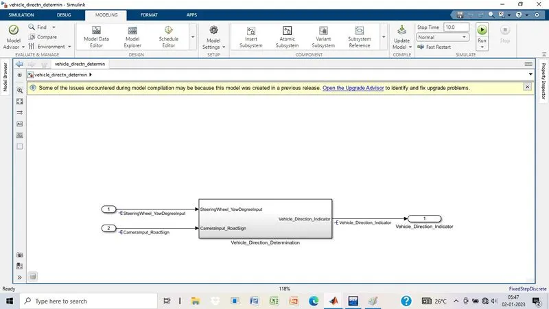
It is the main model for vechicle direction detection, where the inputs are given as SteeringWHeel_YawDegreeInput and CameraInput_RoadDign.

Reqirement_1:
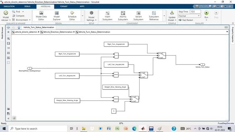
  • In this Requirement1, the steering wheel yaw degree is given as input to the subsystem and this input value is compared against 3 angular values, one each for left turn, right turn & straight drive to tell the steering wheel is turning towards which direction. In this case, the output of the relational operator '==' is equal to 1 only when the 'SteeringWheel_YawDegreeInput' matches with any one of caliberation value then it will give logical 1 or true condition.
  • Three signal switch blocks are used to implement an if-else logic. The output from each relational operator(==) is given to second port of each switch block. The switch will pass input1 (calibration value) when the condition (input2>0) condition is satisfied, else input3 is passed as output.

  • If 'SteeringWheel_YawDegreeInput' does not matches with any one of caliberation value then it will give logical 0 or false condition. Then, it will take the value mentioned in the third port of switch 3. In this case, at the third port, value mentioned is 0 hence, the same is given out as output i.e Vehicle_Turn_Status.

Requirement_2:
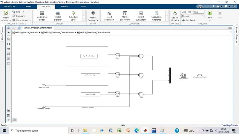
  • In Requirement_2 subsystem, the local signal 'Vehicle_Turn_Status' is fed from 'Requirement1' subsystem and given as an input and is compared against calibration values using the relational operator '=='.
  • If the value matches, then the relational operator (==) gives logical 1 or true value and same is compared in AND operation with input signal from camera i.e.CameraInput_RoadSign which states that when camera actually captures the road sign, then it is compared with caliberation value of road sign values and when it matches, then only output signal (i.e. Vehicle_Direction_Indicator) is provided in the form of boolean values.
  • The output 'Vehicle_Direction_Indicator' will be a three dimension signal having three boolean elements, with the first element to indicate 'Right Turn', second element to indicate 'Left Turn' and third element to indicate 'Straight Drive'.
  • Since, signals such as Vehicle_Turn_Status is already being used in this model hence we proporgate the same signal by clicking on signal and entered '<>' .

Developing SLDD:
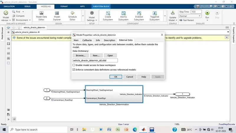
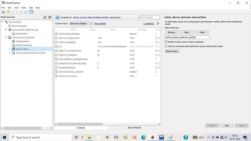
All the inputs and parameters are saved in SLDD so while simulating the model it takes all the value and parameters from Simulink Data Dictionary.

Parameter updates:

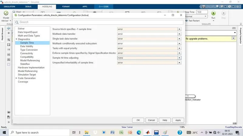
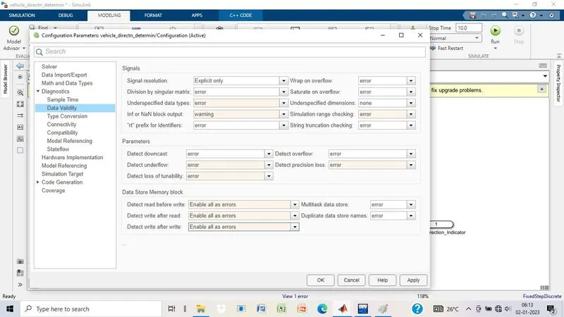
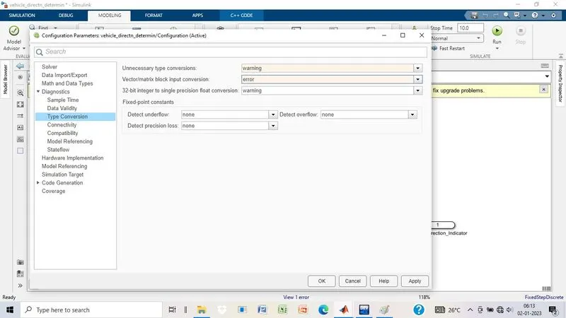
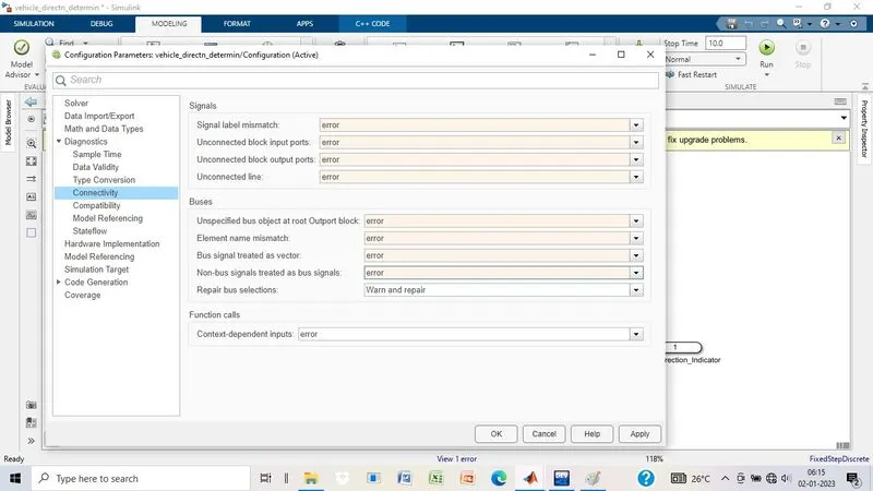
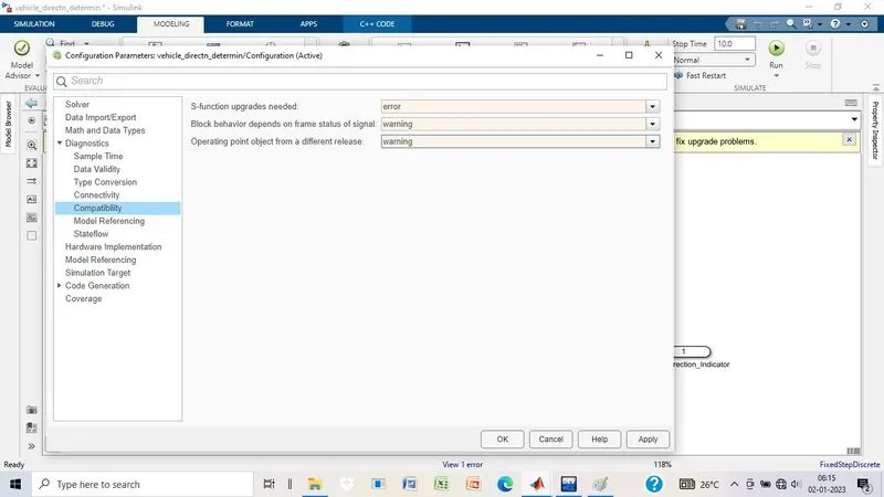
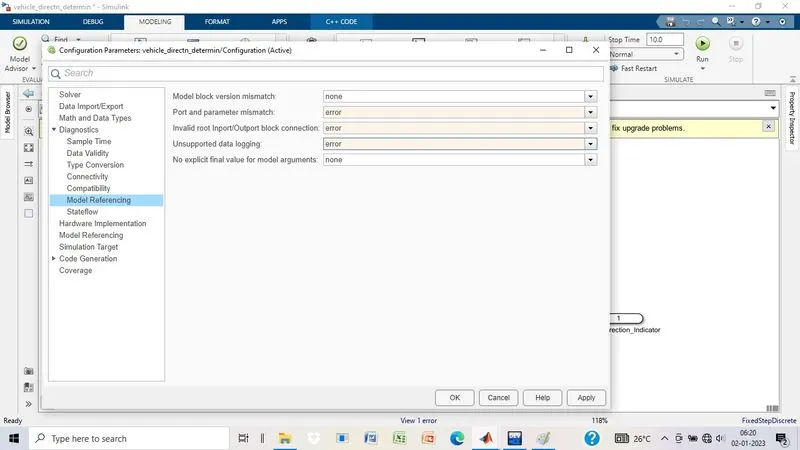
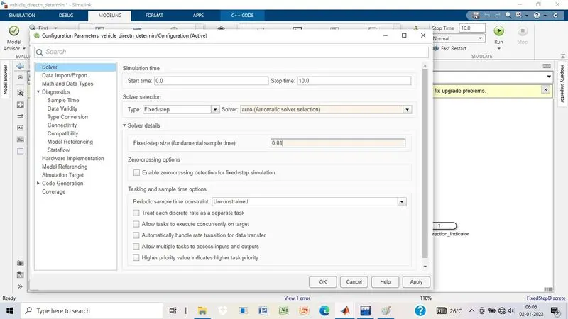
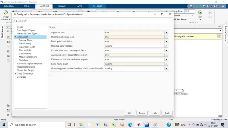
Various configuration parameters are updated as per the code generation and solver type fixed for code generation.
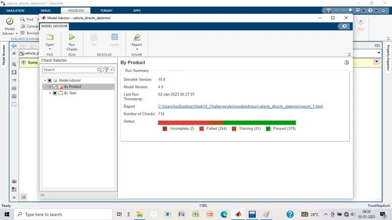
Model Advisor report:
Code Generation:
File Code:

/*
* File: VDD.c
*
* Code generated for Simulink model 'VDD'.
*
* Model version : 1.2
* Simulink Coder version : 9.8 (R2022b) 13-May-2022
* C/C++ source code generated on : Mon Jan 9 07:16:12 2023
*
* Target selection: ert.tlc
* Embedded hardware selection: Intel->x86-64 (Windows64)
* Code generation objectives: Unspecified
* Validation result: Not run
*/
#include "VDD.h"
#include <math.h>
#include "rtwtypes.h"
#include "VDD_private.h"
/* Exported data definition */
/* Definition for custom storage class: ExportToFile */
boolean_T Vehicle_Direction_Indicator[3];/* '<S3>/Signal_Conversion' */
/* Const memory section */
/* Definition for custom storage class: Const */
const int16_T LeftTurn_RoadSign = -120;/* Referenced by: '<S3>/Constant1' */
const int16_T Left_Turn_AngularLimit = -120;/* Referenced by:
* '<S2>/Constant1'
* '<S2>/Constant3'
*/
const int16_T RightTurn_RoadSign = 30; /* Referenced by: '<S3>/Constant' */
const int16_T Right_Turn_AngularLimit = 30;/* Referenced by:
* '<S2>/Right_Turn_AngularLimit'
* '<S2>/Right_Turn_AngularLimit1'
*/
const int16_T Straight_Drive_Steering_Angle = 0;/* Referenced by:
* '<S2>/Constant2'
* '<S2>/Constant4'
*/
const int16_T Straight_RoadSign = 0; /* Referenced by: '<S3>/Constant2' */
/* Real-time model */
static RT_MODEL_VDD_T VDD_M_;
RT_MODEL_VDD_T *const VDD_M = &VDD_M_;
/* Model step function */
void VDD_step(void)
{
/* local block i/o variables */
int16_T Vehicle_Turn_Status;
/* Outputs for Atomic SubSystem: '<Root>/Subsystem' */
/* Switch: '<S2>/Switch' incorporates:
* Constant: '<S2>/Constant1'
* Constant: '<S2>/Constant2'
* Constant: '<S2>/Right_Turn_AngularLimit'
* Inport: '<Root>/SteeringWheel_YawDegreeInput'
* RelationalOperator: '<S2>/Equal'
* RelationalOperator: '<S2>/Equal1'
* RelationalOperator: '<S2>/Equal2'
* Switch: '<S2>/Switch1'
* Switch: '<S2>/Switch2'
*/
if (Right_Turn_AngularLimit == SteeringWheel_YawDegreeInput) {
/* Switch: '<S2>/Switch' incorporates:
* Constant: '<S2>/Right_Turn_AngularLimit1'
*/
Vehicle_Turn_Status = Right_Turn_AngularLimit;
} else {
int32_T tmp;
if (SteeringWheel_YawDegreeInput == Left_Turn_AngularLimit) {
/* Switch: '<S2>/Switch1' incorporates:
* Constant: '<S2>/Constant3'
*/
tmp = Left_Turn_AngularLimit;
} else if (SteeringWheel_YawDegreeInput == Straight_Drive_Steering_Angle) {
/* Switch: '<S2>/Switch2' incorporates:
* Constant: '<S2>/Constant4'
* Switch: '<S2>/Switch1'
*/
tmp = Straight_Drive_Steering_Angle;
} else {
/* Switch: '<S2>/Switch1' incorporates:
* Constant: '<S2>/Constant'
* Switch: '<S2>/Switch2'
*/
tmp = 0;
}
tmp = (int32_T)fmod(tmp, 65536.0);
/* Switch: '<S2>/Switch' incorporates:
* Constant: '<S2>/Constant2'
* RelationalOperator: '<S2>/Equal2'
* Switch: '<S2>/Switch1'
* Switch: '<S2>/Switch2'
*/
Vehicle_Turn_Status = (int16_T)(tmp < 0 ? (int32_T)(int16_T)-(int16_T)
(uint16_T)-(real_T)tmp : tmp);
}
/* End of Switch: '<S2>/Switch' */
/* SignalConversion: '<S3>/Signal_Conversion' incorporates:
* Constant: '<S3>/Constant'
* Constant: '<S3>/Constant1'
* Constant: '<S3>/Constant2'
* Inport: '<Root>/CameraInput_RoadSign'
* Logic: '<S3>/AND'
* Logic: '<S3>/AND1'
* Logic: '<S3>/AND2'
* RelationalOperator: '<S3>/Equal'
* RelationalOperator: '<S3>/Equal1'
* RelationalOperator: '<S3>/Equal2'
*/
Vehicle_Direction_Indicator[0] = ((Vehicle_Turn_Status == RightTurn_RoadSign) &&
CameraInput_RoadSign);
Vehicle_Direction_Indicator[1] = ((Vehicle_Turn_Status == LeftTurn_RoadSign) &&
CameraInput_RoadSign);
Vehicle_Direction_Indicator[2] = ((Vehicle_Turn_Status == Straight_RoadSign) &&
CameraInput_RoadSign);
/* End of Outputs for SubSystem: '<Root>/Subsystem' */
}
/* Model initialize function */
void VDD_initialize(void)
{
/* (no initialization code required) */
}
/* Model terminate function */
void VDD_terminate(void)
{
/* (no terminate code required) */
}
/*
* File trailer for generated code.
*
* [EOF]
*/
C:\Users\hp\Desktop\VDD_ert_rtw\VDD.c
Ln137Col18
has popup
Result:
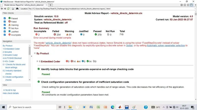
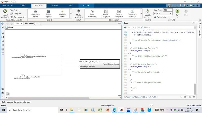
Vechicle Direction detection is modelled as per the requirements, all the signals are defined in the Simulinl Data Dictionary. Also have run the Model Advisor to check the errors.Since there is no error in Model Advisor Report, Code has been generated using Embedded Coder.
Your portfolio, next

Ship work like this
in your own course.

Talk to a career counsellor

Free 20-minute call. We'll map the right course to where you want to work.

By submitting you agree to our Terms and Privacy Policy.