Project 1 (Mini Project on Vehicle Direction Detection
AIM:
1] To Development of MATLAB Simulink model for Vehicle Direction Detection.
2]Tag the requirements to the simulink model; tagging requirement 1 & requirement 2 to their corresponding subsystems.
General Overview:
Identifying the direction of the vehicle is one of the important & diverse features in Autonomous driving & Advanced Driver Assistance Features. This particular sub-feature of identifying the direction of vehicle is basically identifying the direction the vehicle is taking based on the camera input.
Camera reads the road signs & stores into its memory with unique values for left turn, right turn & straight drive. Depending on the direction it is taking, final indication is given to the driver – as an indication if he is driving in the recommended direction or not.
Vehicle Direction Determination can also be coupled along - side features like GPS systems to identify whether the vehicle is reaching its destination in an optimized manner. This sub feature can also be used along with Lane Detection, Highway Warning, Ramp Entry / Exit in Wrong Way Detection etc.
REQUIRENMENTS:
Requirement - 1:
- Steering wheel input as yaw rate (Signal name: SteeringWheel_YawDegreeInput) is the input for this system.
- This is compared against 3 angular values, one each for left turn, right turn & straight drive (Calibration Values: Right_Turn_AngularLimit, Left_Turn_AngularLimit, Straight_Drive_Steering_Angle) to say which specific direction the steering wheel is turning towards.
- Use switch blocks to compare & develop this requirement. Keep this requirement in a subsystem & output of this requirement is a local signal (Signal Name: Vehicle_Turn_Status).
Requirement – 2:
- Keep this requirement as a separate subsystem. Inputs to this requirement are local signal from requirement 1 (Signal Name: Vehicle_Turn_Status) & an input signal from camera (Signal Name: CameraInput_RoadSign), which confirms the occurrence of a road sign.
- Signal Vehicle_Turn_Status is compared against calibration values (Calibration Values: RightTurn_RoadSign, LeftTurn_RoadSign, Straight_RoadSign), if each of them is found equal, then each of the three corresponding output is compared against the camera input signal,
- Using a logical operator block, only one among them is finally given as output signal (Signal Name: Vehicle_Direction_Indicator).
STEP 1:
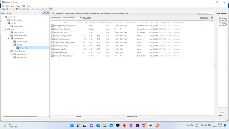
SLDD file :
1]To create sldd file goto MODELING->Link To Data Dictionary
2]Click on NEW
3]Go to the Folder where code is saved.
4]creat a new file with name with underscore dd.
5]Click apply and open
6]As provided copy all the data to sldd file.
STEP 2:
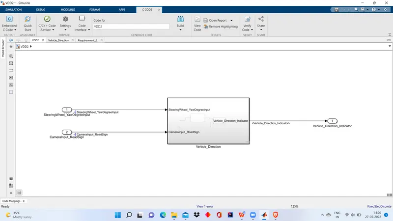
Creation of model.
STEP 3: signal Resolution and requirenment tagging
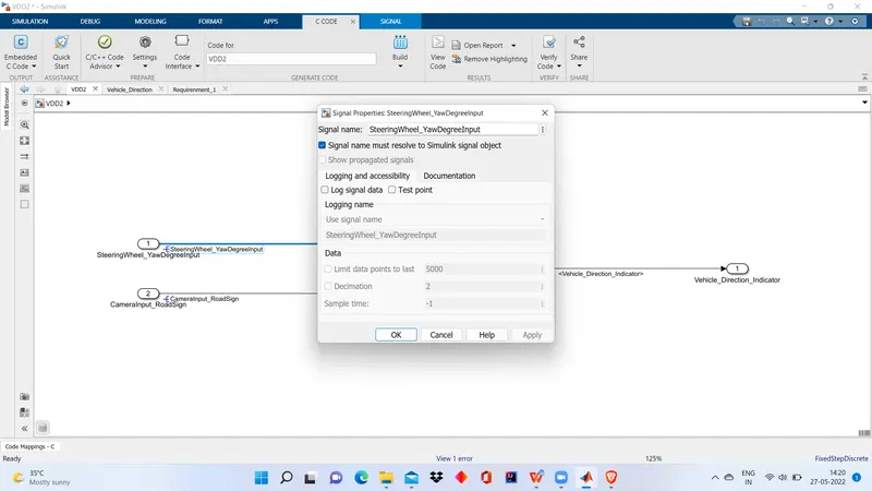
1] After model is created now we have to resolve signals
2]Resolve the signal where it appears first by:
a] Right click on transition line
b]Click on PROPERTIES
c]Type the signal name check the given box as shown below
REQUIRENMENT TAGING
(Due to usw WPS office was not able to to do requirenment taging so according to instruction of support engineer only steps are provided)
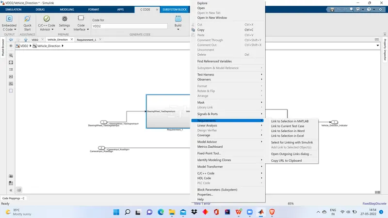
1]Open the word file containg the requirenments
2]Seclect the heading requirenment 1
3]Goto model right click on subsystem created on basis of particular requirenment
4]Right click ->Requirenments-> Link to word seclection in word
5]Taging is done.
STEP 4] Code Generation
1]For code generation Goto APPS
2]APPS->Embeded coder->BUILD
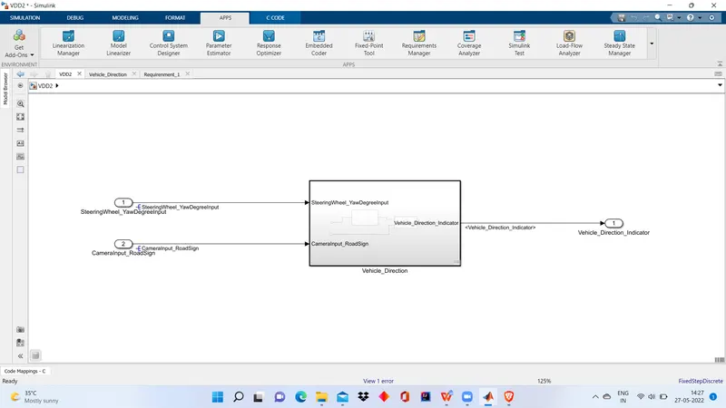
Generated code
/*
 * File: VDD2.c
 *
 * Code generated for Simulink model 'VDD2'.
 *
 * Model version                  : 1.7
 * Simulink Coder version         : 9.5 (R2021a) 14-Nov-2020
 * C/C++ source code generated on : Fri May 27 11:31:44 2022
 *
 * Target selection: ert.tlc
 * Embedded hardware selection: Intel->x86-64 (Windows64)
 * Code generation objectives: Unspecified
 * Validation result: Not run
 */

#include "VDD2.h"
#include "VDD2_private.h"

/* Exported data definition */

/* Definition for custom storage class: ExportToFile */
boolean_T Vehicle_Direction_Indicator[3];/* '/Signal Conversion' */

/* Definition for custom storage class: Localizable */
static int16_T Vehicle_Turn_Status;    /* '/Switch' */

/* Const memory section */
/* Definition for custom storage class: Const */
const int16_T LeftTurn_RoadSign = -120;/* Referenced by: '/Constant1' */
const int16_T Left_Turn_AngularLimit = -120;/* Referenced by: '/Constant1' */
const int16_T RightTurn_RoadSign = 30; /* Referenced by: '/Constant' */
const int16_T Right_Turn_AngularLimit = 30;/* Referenced by: '/Constant' */
const int16_T Straight_Drive_Steering_Angle = 0;/* Referenced by: '/Constant2' */
const int16_T Straight_RoadSign = 0;   /* Referenced by: '/Constant2' */

/* Real-time model */
static RT_MODEL_VDD2_T VDD2_M_;
RT_MODEL_VDD2_T *const VDD2_M = &VDD2_M_;

/* Model step function */
void VDD2_step(void)
{
  /* Outputs for Atomic SubSystem: '/Vehicle_Direction' */
  /* Switch: '/Switch' incorporates:
   *  Constant: '/Constant'
   *  Constant: '/Constant'
   *  Inport: '/SteeringWheel_YawDegreeInput'
   *  RelationalOperator: '/Compare'
   *  RelationalOperator: '/Compare'
   *  Switch: '/Switch1'
   */
  if (SteeringWheel_YawDegreeInput > 0) {
    /* Switch: '/Switch' incorporates:
     *  Constant: '/Constant'
     */
    Vehicle_Turn_Status = Right_Turn_AngularLimit;
  } else if (SteeringWheel_YawDegreeInput < 0) {
    /* Switch: '/Switch1' incorporates:
     *  Constant: '/Constant1'
     *  Switch: '/Switch'
     */
    Vehicle_Turn_Status = Left_Turn_AngularLimit;
  } else {
    /* Switch: '/Switch' incorporates:
     *  Constant: '/Constant2'
     *  Switch: '/Switch1'
     */
    Vehicle_Turn_Status = Straight_Drive_Steering_Angle;
  }

  /* End of Switch: '/Switch' */

  /* SignalConversion: '/Signal Conversion' incorporates:
   *  Constant: '/Constant'
   *  Constant: '/Constant1'
   *  Constant: '/Constant2'
   *  Inport: '/CameraInput_RoadSign'
   *  Logic: '/AND'
   *  Logic: '/AND1'
   *  Logic: '/AND2'
   *  RelationalOperator: '/Relational Operator'
   *  RelationalOperator: '/Relational Operator1'
   *  RelationalOperator: '/Relational Operator2'
   */
  Vehicle_Direction_Indicator[0] = ((Vehicle_Turn_Status == RightTurn_RoadSign) &&
    CameraInput_RoadSign);
  Vehicle_Direction_Indicator[1] = ((Vehicle_Turn_Status == LeftTurn_RoadSign) &&
    CameraInput_RoadSign);
  Vehicle_Direction_Indicator[2] = ((Vehicle_Turn_Status == Straight_RoadSign) &&
    CameraInput_RoadSign);

  /* End of Outputs for SubSystem: '/Vehicle_Direction' */
}

/* Model initialize function */
void VDD2_initialize(void)
{
  /* Registration code */

  /* block I/O */

  /* custom signals */
  Vehicle_Turn_Status = 30;
}

/* Model terminate function */
void VDD2_terminate(void)
{
  /* (no terminate code required) */
}

/*
 * File trailer for generated code.
 *
 * [EOF]
 */
Creating the test cases :
after understanding the model folowing are the created TEST CASES
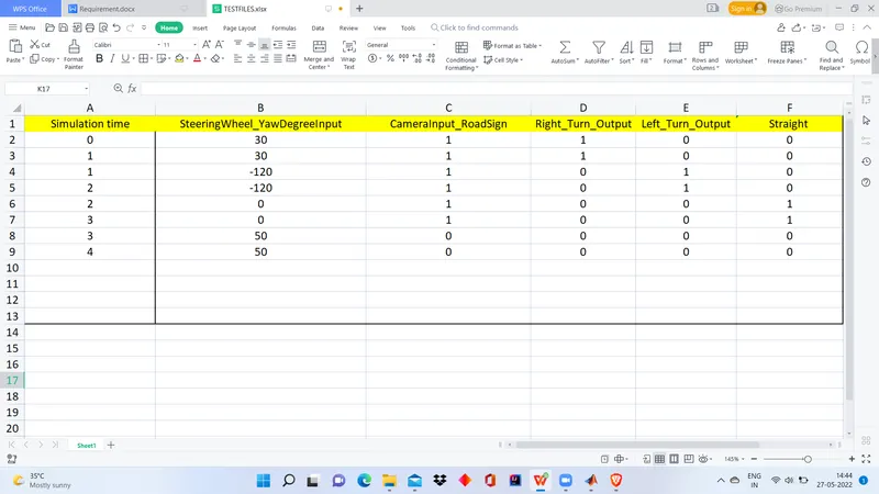
gIVE this test cases as input for Signal builder for MIL and SIL testing
by option IMPORTFROMFILE option in signal builder
MIL generation :
1]Right click on Subsystem
2]Click on Create test Harness
3]seclect Input as SIGNAL BUILDER
4]Output as OUTPORT
5]Click OK
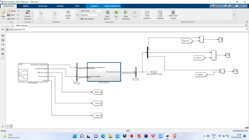
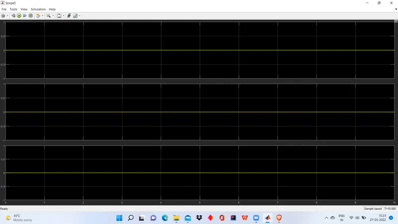
1]Comparing the expected outputs that is output stored in signal builder with the actual output obtained from scope connected to the demux .
2]Here we can we that results are matching meaning out model works perfectly as we assumed in TEST CASES.
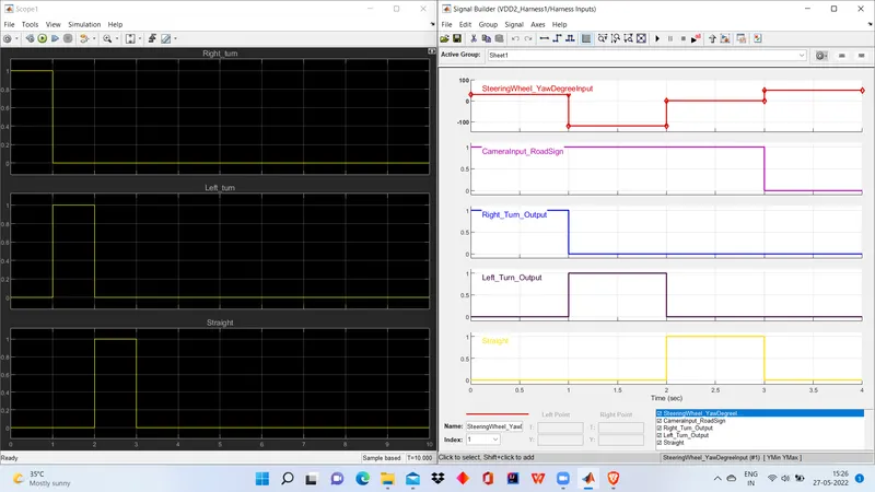
3]To confirm that there is no difference between expected and actual output both outputs are subtracted and viewed in scope block.
4]The results in scope is a flat line at 0 throughout for all the signals .
5]This cornfirms our model is working perfectly.
SIL generation :
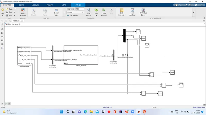
1]Right click on Subsystem ->Block parameters ->Treat as atomic
2]Right click on Subsystem ->Click on Create test Harness
3]seclect Input as SIGNAL BUILDER
4]Output as OUTPORT
5]Click OK
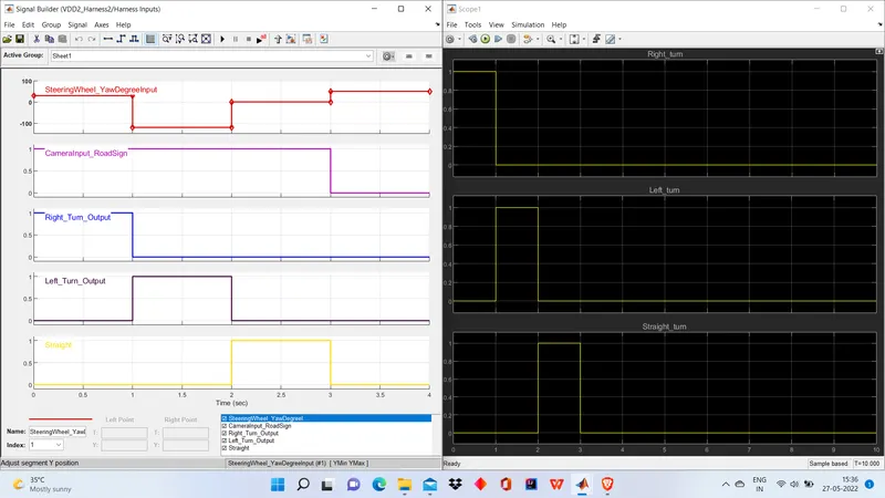
1]Comparing the expected outputs that is output stored in signal builder with the actual output obtained from scope connected to the demux .
2]Here we can we that results are matching meaning out model works perfectly as we assumed in TEST CASES.
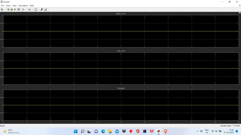
3]To confirm that there is no difference between expected and actual output both outputs are subtracted and viewed in scope block.
4]The results in scope is a flat line at 0 throughout for all the signals .
5]This cornfirms our model is working perfectly.
Goto MODEl ADvisor and check for mab guidlines and generate report
report is provided in zip file