Project 1 (Mini Project on Vehicle Direction Detection
Mini Project - Vehicle Direction Determination
Aim:-
To identify the direction of the vehicle mainly through the camera input (Camera reads the road signs & stores them into its memory with unique values for the left turn, right turn & straight drive.) and guide the driver (with a suitable indication) whether he is driving in the recommended direction or not.
Simulink Model:
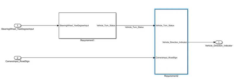
The below image shows the Simulink model for Vehicle direction determination. It has been prepared in compliance with the requirements asked. The Model takes input from the camera reading (which reads the road signs) and also the steering wheel angular position so as to determine the direction of the vehicle by suitable comparison. The subsystems have been modeled as per the corresponding requirement. The output of the model is the vehicle direction indicator for the driver which guides him whether he is driving in the recommended direction or not.
Requirement-1, Subsystem:-
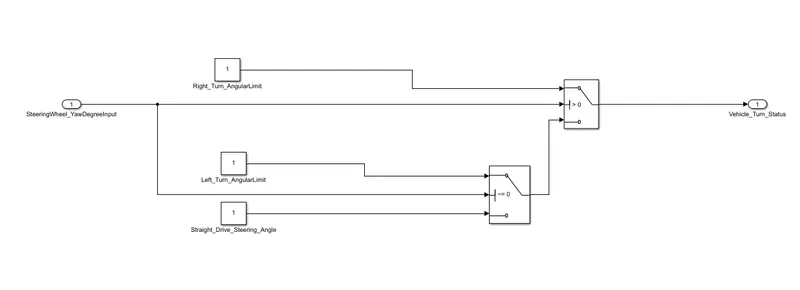
This subsystem is modeled in compliance with Requirement 1 of the project which states below and has been tagged to the subsystem.
Requirement-1:
- Steering wheel input as yaw rate (Signal name: SteeringWheel_YawDegreeInput) is the input for this system.
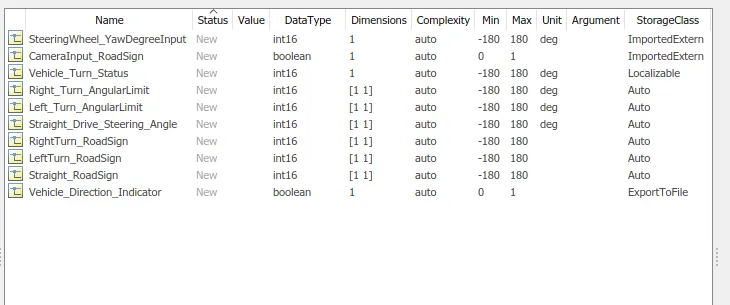
- This is compared against 3 angular values, one each for the left turn, right turn & straight drive (Calibration Values: Right_Turn_AngularLimit, Left_Turn_AngularLimit, Straight_Drive_Steering_Angle) to say which specific direction the steering wheel is turning towards.
- The switch blocks are used to compare & develop this requirement. This requirement is kept in a subsystem & the output of this requirement is a local signal (Signal Name: Vehicle_Turn_Status).
Requirement-2, Subsystem:-
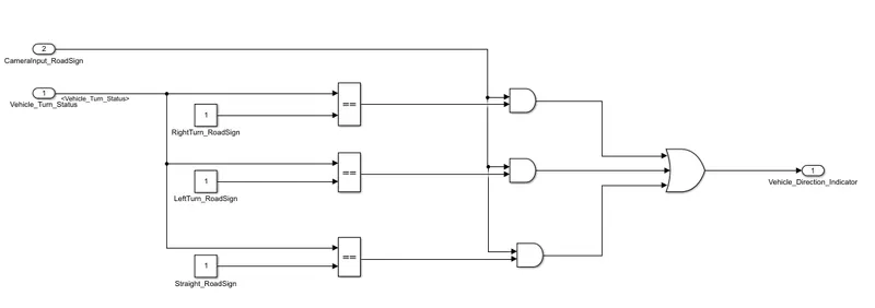
This subsystem is modeled in compliance with Requirement 2 of the project which states below and has been tagged to the subsystem.
Requirement–2:
- This requirement is kept as a separate subsystem. Inputs to this requirement are the local signal from requirement 1 (Signal Name: Vehicle_Turn_Status) & an input signal from the camera (Signal Name: CameraInput_RoadSign), which confirms the occurrence of a road sign.
- Signal Vehicle_Turn_Status is compared against calibration values (Calibration Values: RightTurn_RoadSign, LeftTurn_RoadSign, Straight_RoadSign), if each of them is found equal, then each of the three corresponding output is compared against the camera input signal,
- Using a logical operator block, only one among them is finally given as an output signal (Signal Name: Vehicle_Direction_Indicator).
Data Dictionary:
A suitable data dictionary has been created for the model as shown below.
Result:
The Vehicle direction indicator indicates direction as per the comparison of camera input and steering wheel angular position comparison.
The Simulink model has been run successfully. It is attached as the zip file with Simulink Data Dictionary and Requirement data in a word file.
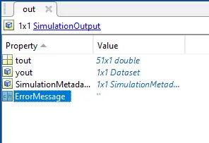
Below is the workspace snap after running the model.