Project 1-Meshing of Rear Wheel Holder challenge
Aim
To mesh the given component with the size of 5 Units following the quality criteria and assign thickness to the component using Hypermesh.
Procedure
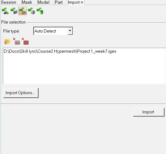
Imported the CAD geometry using the import geometry option on Hypermesh. As it supports the .igs file hence the challenge .iges file is successfully opened. Chose the optistruct profile to carry out the preprocessing.
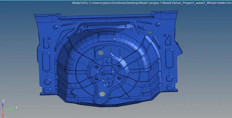
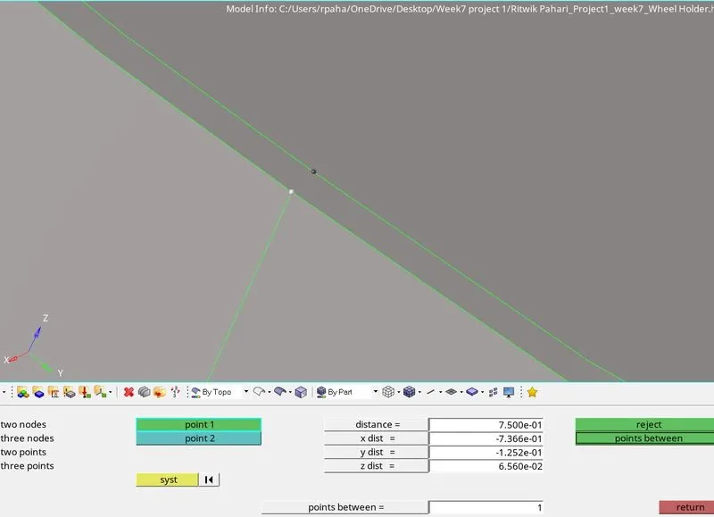
Measurements were taken for the sheet metal component (Rear Wheel Holder) using Tools>Distance>two points.
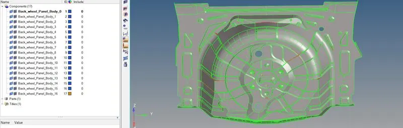
After opening the file in the components section it was seen that 17 components were there and according to the measurement taken for all the components resulting in the whole component is uniform hence organized all the 17 components to a single component using Tools>Organize>collector>Selected all the components by collector>selected destination component>move.
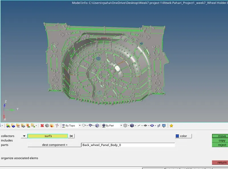
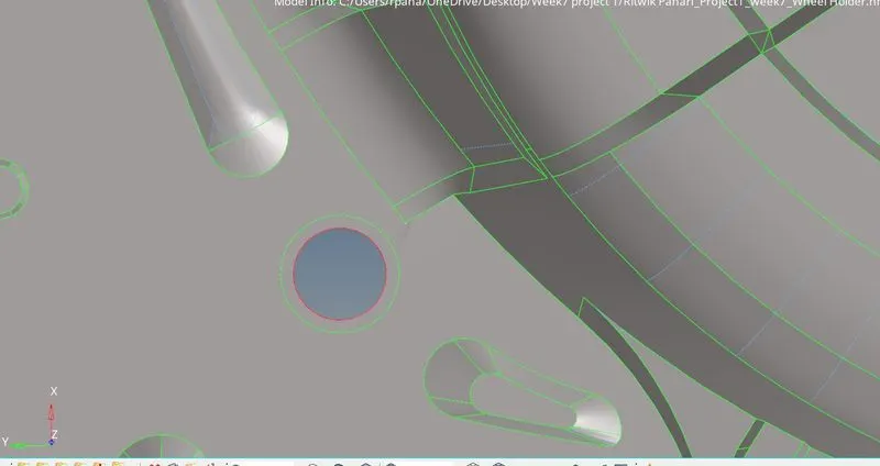
Before generating the midsurface it can be seen that there are cracks, missing surface, overlapping surface, damaged surface, unnecessary button, point issues in the original component.
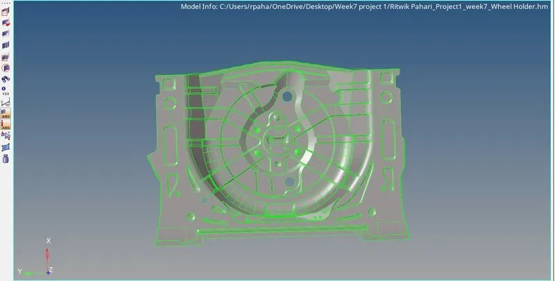
Hence carried the geometry cleanup for the whole component. Though we can generate midsurface and carry out geometry cleanup which will save much time. Used the toggle edge, filler surface, replace points, release points, project point, supress edge in Quick edit panel extensively with spline, ruled surface creation to perform cleanup.
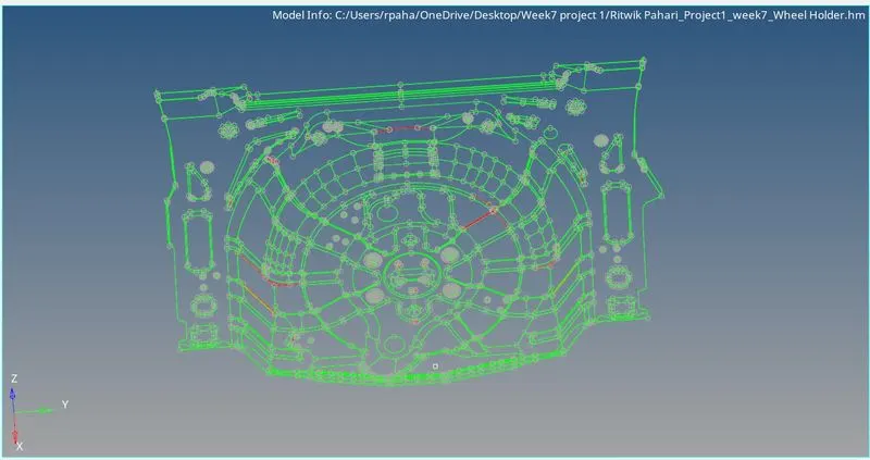
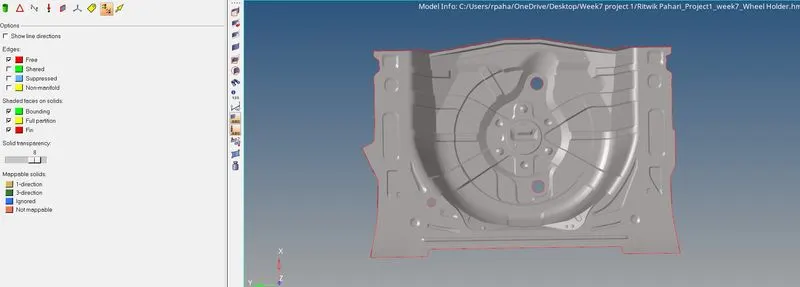
Used the visualisation tab to view the free edges as the component is large and has many minute feature lines. Unticked the green(shared), yellow(non-manifold) and cyan(supressed) option with only the red option ticked and viewed the model.
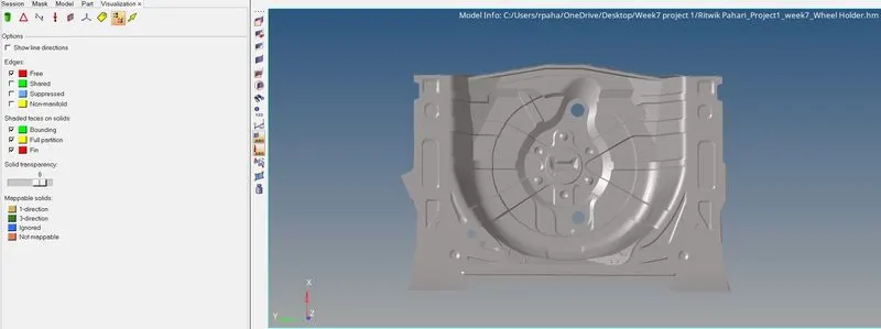
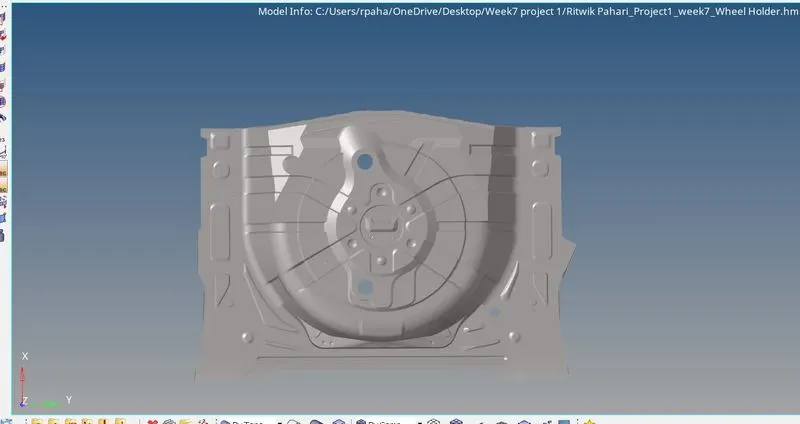
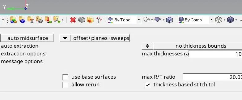
Before generating the midsurface at first performed the solid deletion on the component. Used delete option with solid selection then clicked on delete entity. Then used the Geometry>midsurface>automidsurface>extract option with extraction options as "offset+planes+sweep" to generate the midsurface.
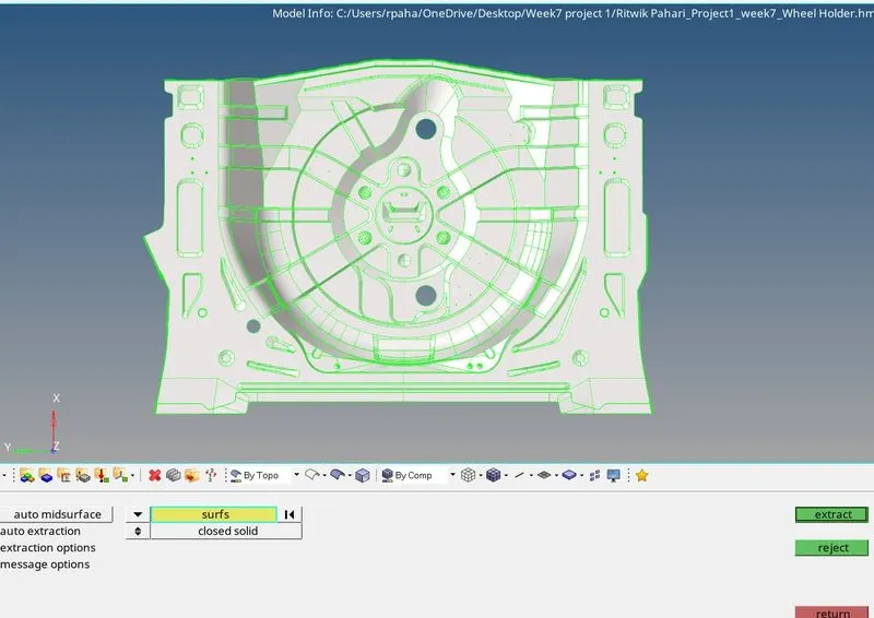
Removed the buttons in the generated midsurface because it will be difficult to capture those areas as well mesh flow will not be proper.

Used the visualisation tab again to view the free edges if there was any in the bulk of the midsurface.
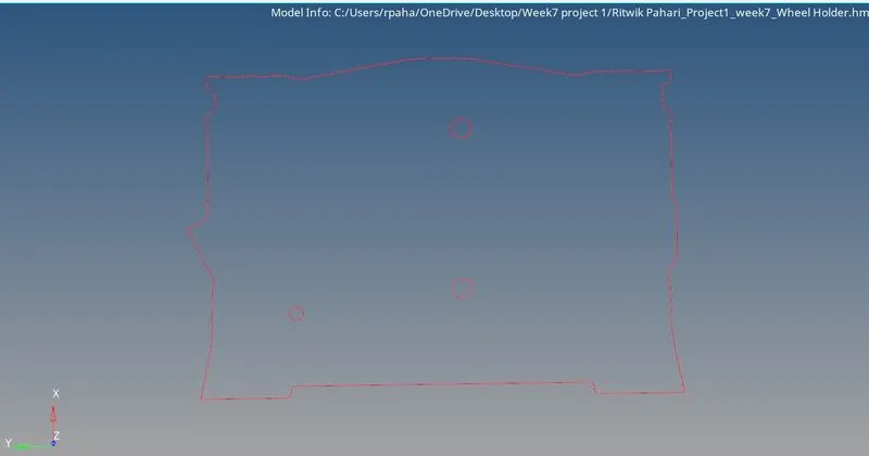
When viewed under wireframe geometry option:
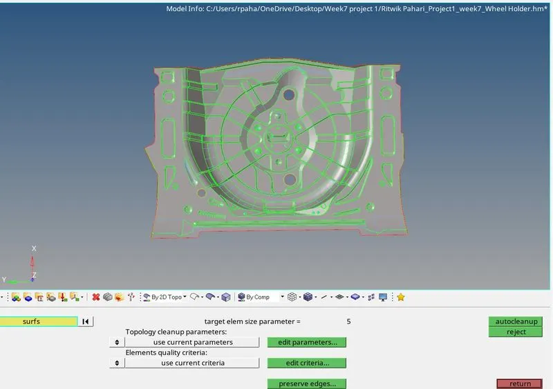
Geometry checkup for the whole component is performed using autocleanup by providing the target element size as 5 in both parameter settings and criteria settings. Also used toggle, split, supress, replace edge options wherever required especially while removing some of the construction lines.
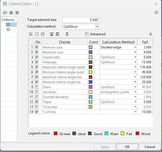
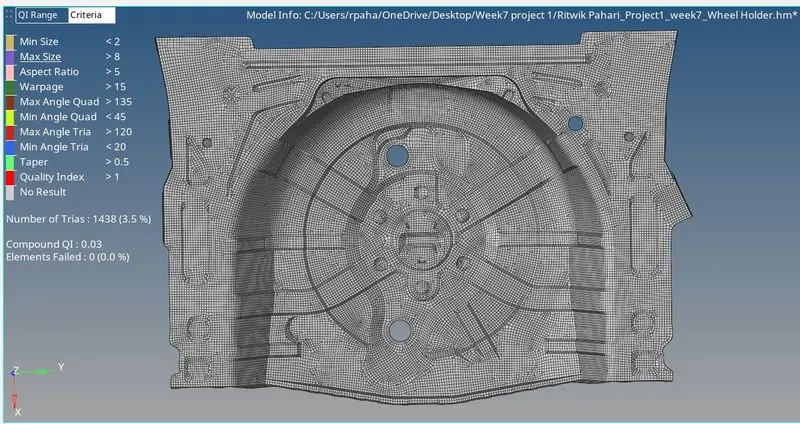
Now quality criteria is given in the question only which is as under:
Target Element Length = 5 Units
| S.N | Quality Criteria | Value |
| 1 | Aspect Ratio | 5 |
| 2 | Skewness | 45 |
| 3 | Warping | 15 |
| 4 | Taper | 0.5 |
| 5 | Min. Length | 2 Units |
| 6 | Max. Length | 8 Units |
| 7 | Min angle Quad | 45 |
| 8 | Max angle Quad | 135 |
| 9 | Min angle Tria | 20 |
| 10 | Max angle Tria | 120 |
| 10 | Tria % | 10 |
Now quality criteria is provided for quality checks so that the component is devoid of quality issues so that boundary conditions and loads can be applied further.
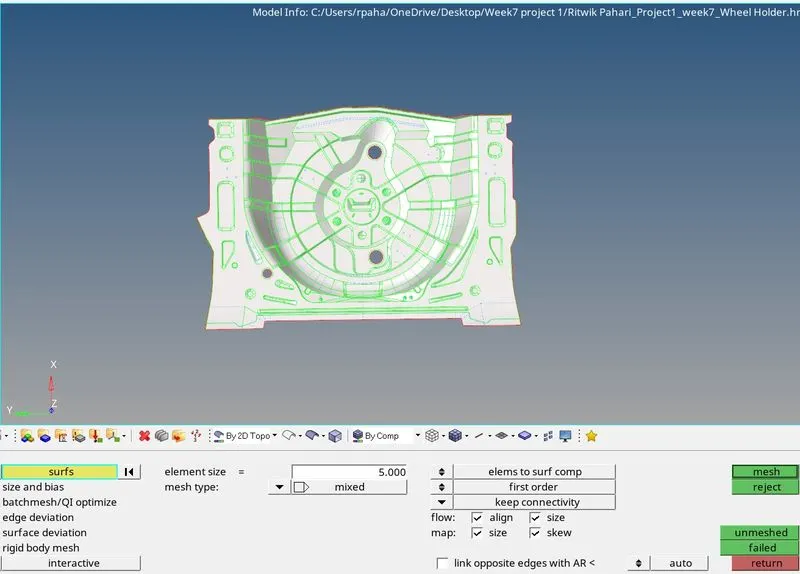
Then went to the 2D option and clicked on automesh. Given the element size as "5" units and selected the mesh type as "mixed", selected all the sufaces of the misurface using surfs>displayed and then meshed the component clicking on the mesh command.
Used the automesh and rebuild mesh command to achieve better mesh flow, used qualityIndex>cleanuptools> drag tria element, Combine, Split, replace to remove trias at the edges and the boundaries and also used this to combine opposite trias using combine option in the element edit option. After all these, viewed the component "By Quality Criteria" and used the quality index with Fail as a threshold and cleared the failed element quality using the cleanup tools>Element optimize, Place node, Node optimize, Replace nodes etc.
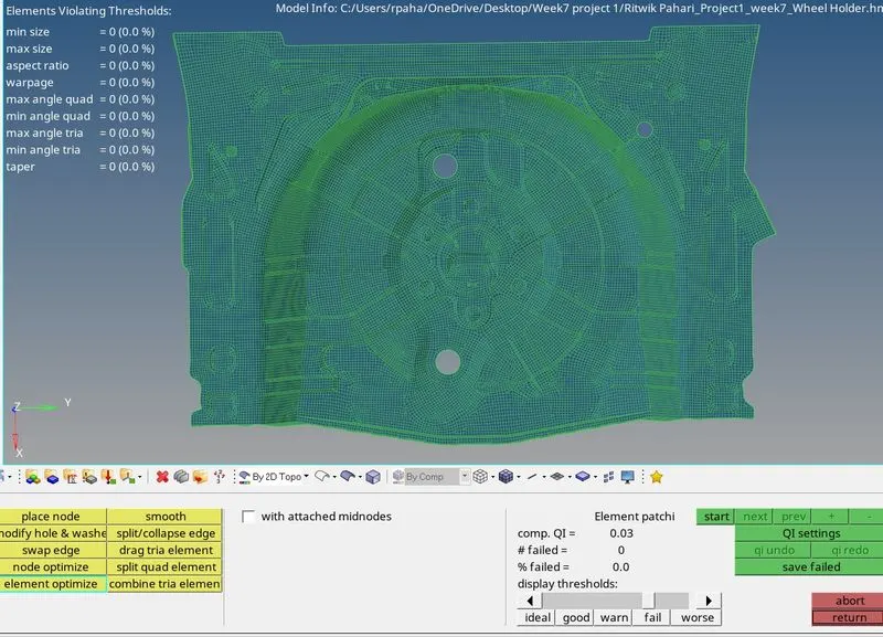
Also align the nodes using align nodes option.
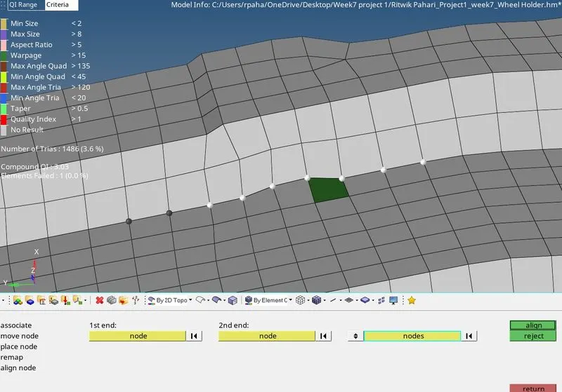
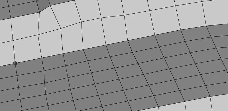
Also used Tools>Check elements and checked for all given quality criterias one by one and cleared the quality accordingly.

Then checked for the free edges using Tools>Edges>Elements>Displayed>Find Edges and checked for any cracks or edges in the bulk area where it should not be, by giving the tolerance values from 0.1, 0.2 to 2 (Min Element Size). As in this step I coudn't find any crackes and mis-attachment between the element edges, hence deleted the edges and proceeded to the next step.

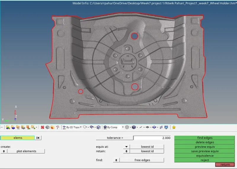
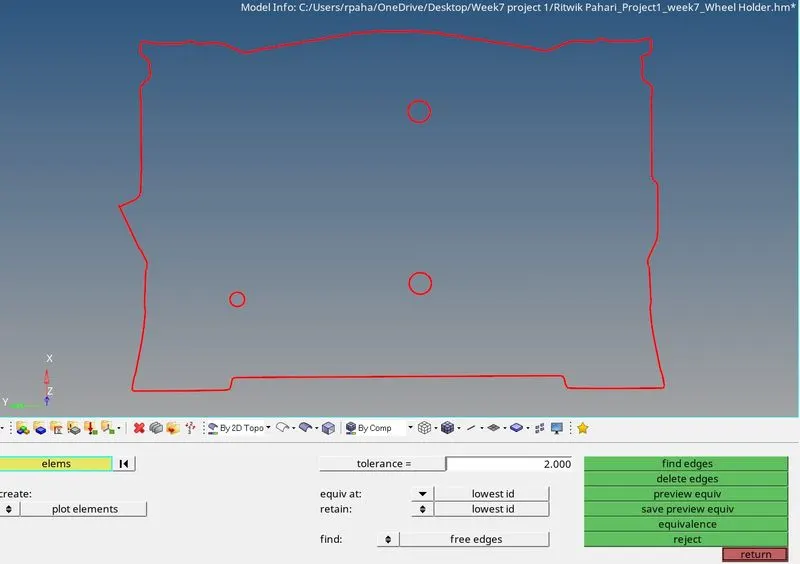
After this used Tool>Check elements>Duplicates>Save failed>mask-element retrieved>reverse>delete to find out the presence of duplicate elements and delete them respectively. Also used shrink element option to view duplicates if present.

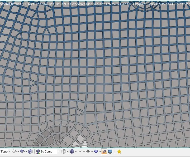
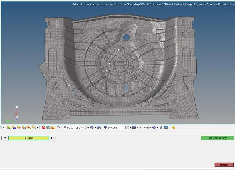
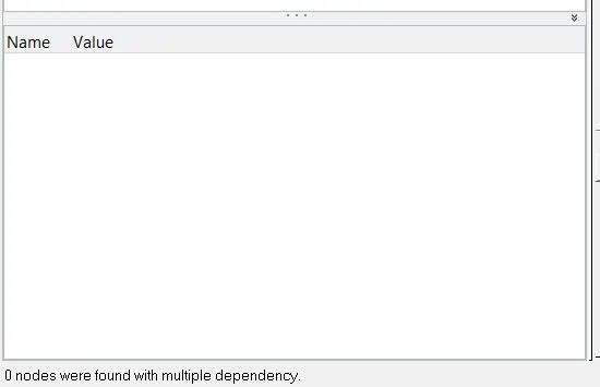
After this checked for Dependency by Tools>Dependency .
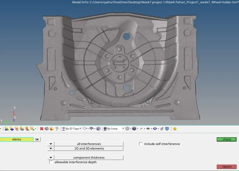
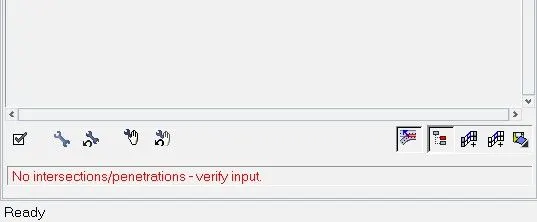
Then checked for Intersections/Penetrations by using Tools>Penetrations>Elements-Displayed>check and then found no intersections/penetrations.
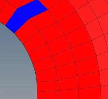
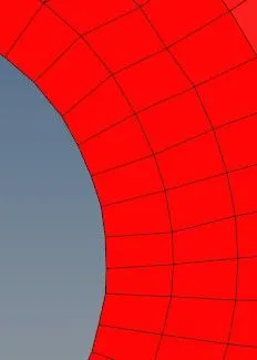
To check for normals used Tools>Normals>Display. Identified the elements which were not oriented like all the other elements and rectified those elements.
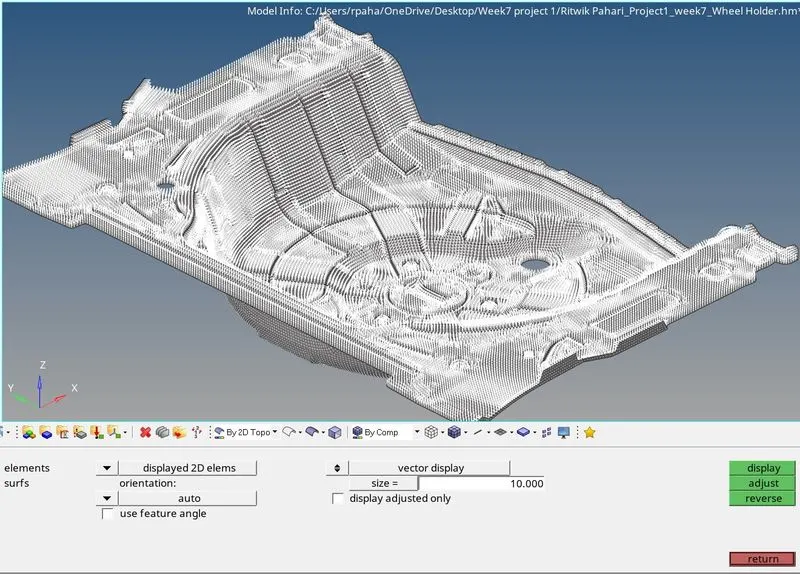
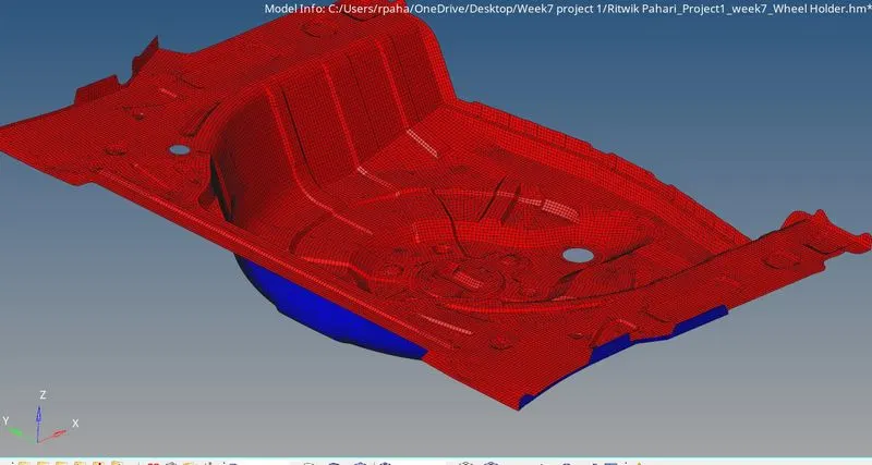
Also viewed the normals in vector representation:
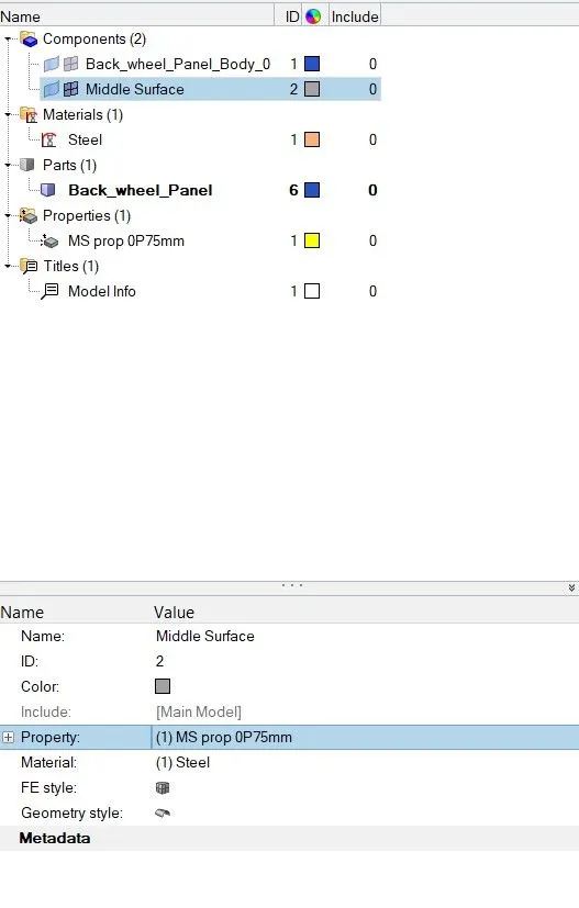
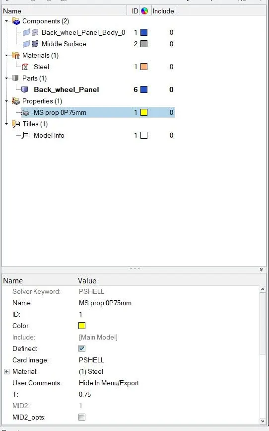
Created a property and material for the midsurface component and provided the thickness as 0.75mm and assigned the material and property to the midsurface component so that the component and mesh can be viewed with 2D detailed representation.
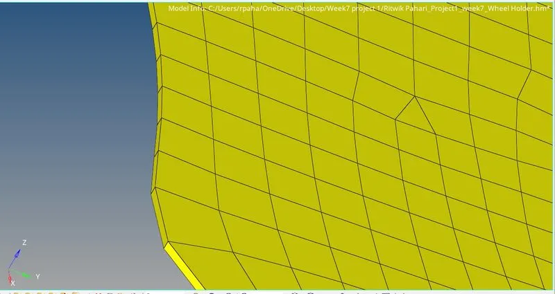
Viewed when "2D detailed element representation" option is turned on:
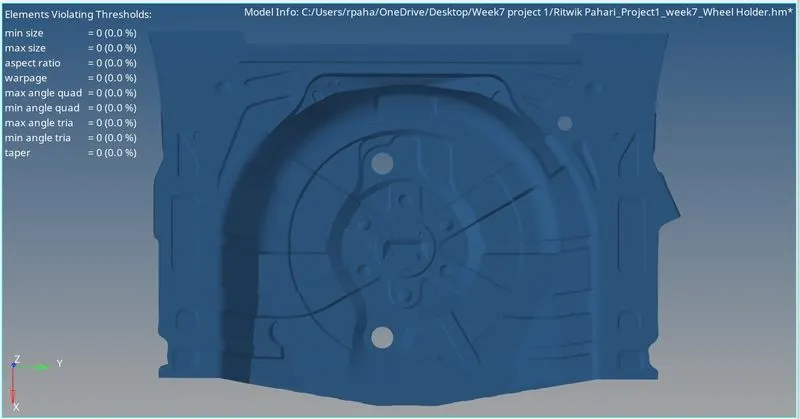
When viewed with quality criteria:
Learning Outcomes
At the end of this challenge I am more familiar with Hypermesh workflow, can perform cleanup, can generate mid surface, can perform defeaturing, can generate mesh with the given quality criteria.
Conclusion
Hence, the given component with target element length of 5 Units is meshed with the given quality criteria and using Hypermesh.