Project 1-Meshing of Rear Wheel Holder challenge
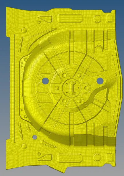
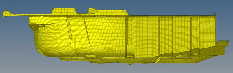
Meshing of rear wheel holder (spare wheel floor panel)
aim: To perform preprocessing on the given Rear Wheel Holder [Spare Wheel Floor Panel] Sheet Metal component using hypermesh preprocessing software.
Objective -
- To generate the mid surface manually and do a geometry clean up on the component.
- To generate a mesh and to get a proper mesh flow on the given component with low tria concentration.
- To check the elements quality according to the given quality criteria.
- To assign a thickness for the component.
Procedure -
initially importing a given CAD geometry into hypermesh. There are file formates like IGES,STEP,Parasolid where we can import these file formats into any CAD,CAE Softwares. But in hypermesh we can only import three file formates like IGES [Initial Graphics Exchange Specification].
While importing the file into the graphical user interface,Be sure whether the file is .step or .iges file. File > Import > Import Model > File type > Open File > Import File.
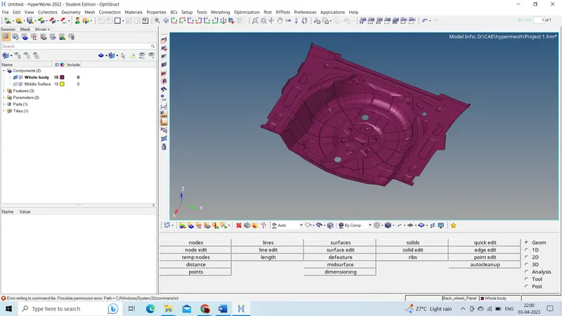
Before working on the model.We have to check the geometry if there are any errors like
- Damaged Geometry.
- Free edges in unnecessary areas.
- Unnecessary points on the lines.
- Unnecessary Connections and connectivity error.
- There are some free edges in the model.
So clear that free edges in the parent component,Then only you can extract mid surface properly without any glitches in the mid surface geometry.
While inspecting the model,It is a spare wheel floor panel which is used to keep the spare wheel in the car. While observing the model,There are 17 [Seventeen] components in the model. Organize them to a single component or delete the unnecessary components.
 We use organize tool to (re)organize your database by copying or moving data (entities) among collectors, includes, or parts. Select an entity type to copy/move, then use the selector to select specific entities to copy/move. The current collector serves as the default destination.
Elements can be copied/moved into component collectors or groups.Lines, surfaces, solids, points, and connectors can be copied/moved into component collectors. Here we are selecting the collectors and we are organizing it to one collector.
Tool >> Organize >> Collector SubPanel >> Switch to Surfaces >> Select by Collector >> Move.
Now go and measure the distance in every region. We are ensuring whether some regions of this component having uniform thickness or not. The component given to us is sheet metal component. The thickness of this stepney floor panel is 0.75 mm. You can measure the thickness by two methods.
For this component,I'm using auto mid surface extraction. Auto Midsurface is used to to extract the midsurface of a more complicated group of surfaces that represent a solid part in one step. I'm extracting midsurface by Offset + Planes + Sweeps,Because this component has many features and sweeps.
Offset + planes + sweeps-It is used to identify the places where a piece of plane or a piece of a sweep surface can be used as a middle surface. A middle surface is constructed at the remaining places in the model, for example the places where planar or sweep surface pieces cannot be used as a middle surface, by the same algorithm as in offset via the offset of the model's sides.
Geom >> Mid surface >> Auto Midsurface >> Extraction process (Offset + Planes + Sweeps) >> Auto Extraction (Closed Volume) >> Surfaces (Displayed) >> Extract.
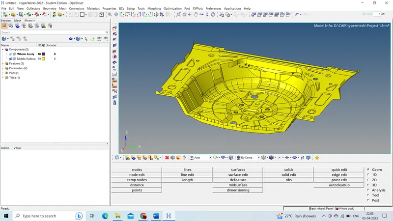
For achieving proper mesh flow, necessary splits are done on the mid surface in a rectangular manner. With the help of quick edit options, unwanted surface lines are toggled, and new ones are created with node to node or with node to line commands. Auto mesh is generated in each of the rectangular boxes, with five units as element size and mixed element type. Since the rectangular sections are made, all quad elements will be generated if any tria is formed in a particular area. They can be removed either by remeshing or with cleanup tools in the quality index. Other than these options dragging trias out of the mesh, combining two opposite trias, splitting, combining, and creating elements, generate maximum quads and least tria elements.
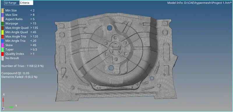
Smoothing and element optimization is done to ensure proper flow and orientation of the mesh. Finally, element check is done by assigning the criteria as:
Target Element Length = 5 Units
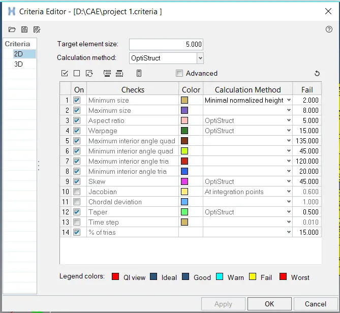
With these above criteria, the generated mesh is checked for each condition; if criteria fail to fall under the requirements, manual mesh methods can correct the mesh.
Now start meshing on the surfaces,Go to 2D >> Automesh Panel >> Surfaces >> Element size = 5mm > Mesh Type : Mixed >> Check for align and size >> Mesh.
To get a good flow of mesh it is recommended to cut the part into Square sections and mesh it from each surface. These lines will help in bringing a good flow in the mesh.
While meshing we will encounter many element errors which must be corrected by us using Quality Index >> Element clean up. We must use a combination of Drag trias, Split, Combine and move the node to clear them.
Since this is a complex part some errors like warpage and minimum length cannot be avoided. In this case, we will have to make the decision if it is okay to keep the error or remove it while compromising with the feature capture.
Conclusion:
For the given sheet metal model we have extracted the mid surface and meshed it with minimum errors for the given quality criteria. Also, the features were captured accurately without any hindrance to the mesh.
Final mesh model: