Project 1-Meshing of Rear Wheel Holder challenge
Project 1-Meshing of Rear Wheel Holder challenge
AIM: - To perform pre-processing on the given Rear Wheel Holder Model using Hyper mesh.
OBJECTIVE:-
- To Extract the mid surface.
- To clean and defeature the Mid surface so as to avoid any minimum length errors while meshing.
- To Mesh the mid surface with the given element Quality criteria and maintaining proper mesh flow.
- To Clear all elements that are failing any Quality criteria.
- To assign thickness to the mesh according the component.
- To checking for free edges.
THEORY:
The component given to us is car stepney spare wheel floor panel. This component is a sheet metal component. For the plastic and Sheetmetal component with the thickness less than 6mm, we have to take a mid-surface and then we have to mesh. Sheet metal is metal formed by an industrial process into thin, flat pieces. Sheet metal is one of the fundamental forms used in metal working, and it can be cut and bent into a variety of shapes.
Countless everyday objects are fabricated from sheet metal. Thicknesses can vary significantly; extremely thin sheets are considered foil or leaf, and pieces thicker than 6 mm (0.25 in) are considered plate steel.
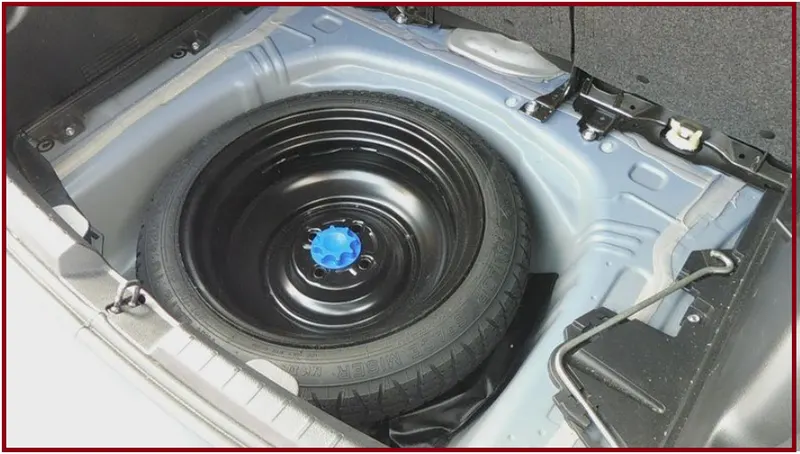
- A spare tire (or stepney) is an additional (tire or tyre) carried in a motor vehicle as a replacement for one that goes flat, has a blowout, or has another emergency.
- Spare tire is generally a misnomer as almost all vehicles actually carry an entire wheel with a tire mounted on it as a spare rather than just a tire, as fitting a tire to a wheel would require a motorist to carry additional, specialized equipment. However, some spare tires ("space-saver" and "donut" types) are not meant to be driven long distances. Space-savers have a maximum speed of around 50 mph (80 km/h).
- When replacing a damaged tire, placing the compact spare on a non-drive axle will prevent damage to the drivetrain. If placed on a drivetrain axle, the smaller-diameter tire can put stress on the differential causing damage and reducing handling.
- A structural shear panel for forming a floor panel for support by a vehicle frame is formed by a composite of top and bottom sheets and a core with a vacuum infused resin.
- The core is formed of top and bottom layers each formed from a honeycomb panel defining an array of hexagonal tubular cells with walls which extend in the thickness direction filled with a foam material.
- A third layer is located between the first and second layers and is formed of a material such as foam, rubber or cork which is free from tubular cells in the thickness direction and free from rigid structural members in the thickness direction to reduce communication of sound through the panel.
PROCEDURE/STEPS: -
- import cad geometry file
we are importing a given CAD geometry into hyper mesh. There are file formats like IGES, STEP, Parasolid where we can import these file formats into any CAD, CAE Software’s. But in hyper mesh we can only import three file formats’ like
- IGES [Initial Graphics Exchange Specification].
- STEP [Standard for the Exchange of Product Model Data].
- Solid works.
IGES, STEP, these two are standard file formats which are used most in industries. But now a days in industries, they are also using Parasolid file format. While importing the file into the graphical user interface, Be sure whether the file is .step or .iges file.
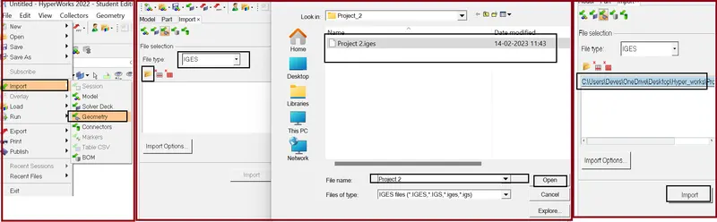
Command: File >> Import >> Model >> Locate the file directory (as per given figure) >> hit Open >> hit Import.
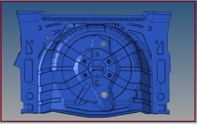
- Checking for solid surfaces:
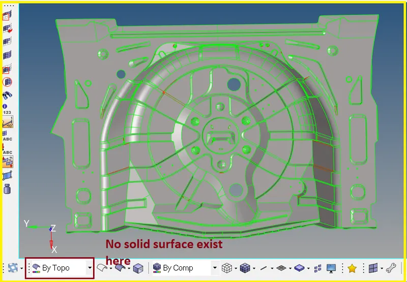
Switch to the topo mode and examine whether the solid exist in the component or not, if solids exist, Delete the solids because we are doing 2d meshing on the component.
for deleting the solid surface, we have to select the delete tool and change the option to "solid" in which it only selects the solid surface if available and delete.
- Inspecting The Model
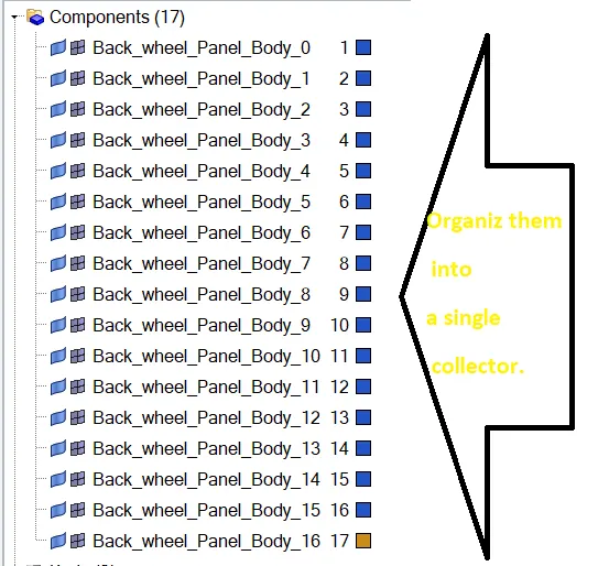
While observing the model, there are 17 [Seventeen] components in the model. Organize them to a single component or delete the unnecessary components.
Tool >> Organize >> Collector SubPanel >> Switch to Surfaces >> Select by Collector >> Move.
- Geometric Clean Up on the Parent Component
Here I’m doing geometric clean up on the parent component, there is no need to work on parent geometry, if you want you can work on parent geometry or it's fine.
Now fix this damaged surface by deleting the surface.
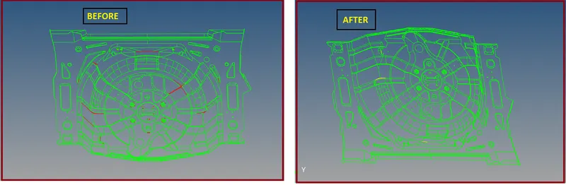
We can fix the geometry by quick edit tools.

There some sub tools in the quick edit panel, I have described every tool below, Have a look.
- Geometry >> Quick edit >> Split surf-line
In this, select a node and select a line to split the surface, here the split will be perpendicular to the line chosen.
- Geometry >> Quick edit >> split surface node.
Select two locations of the nodes to split the surface and then select an additional node to continue to split the surface.
- Geometry >> Quick edit >> Adjust/set density.
After meshing a particular surface. We can adjust the mesh density by using this tool. While meshing we will increase the nodes to get a proper mesh flow. We can also increase nodes after meshing by using this tool.
- Geometry >> Quick edit >> Release points.
Drag and select the surface, where you want release the points. After releasing the points. The free edges will exist.
- Geometry >> Quick edit >> Replace points.
Move points from their current locations to the locations of other points, where we want them to replace it.
- Geometry >> Quick edit >> Add/Remove points.
Use window selection (with the left mouse button and right mouse button) to add and remove any points within the selection box.
- Geometry >> Quick edit >> Add points on line.
Specify the number of points that we wish to add to that line, and then select the desired line in our model.
- Geometry >> Quick edit >> Delete surface.
Select the surface which we need to eliminate and delete it.
- Extract the Mid Surface
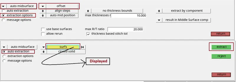
For this component, we are using auto mid surface extraction.
Auto Mid surface is used to extract the mid surface of a more complicated group of surfaces that represent a solid part in one step.
I'm extracting mid surface by Offset this component.
Geom >> Mid surface >> Auto Midsurface >> Extraction process (Offset) >> Auto Extraction (Closed Volume) >> Surfaces (Displayed) >> Extract.
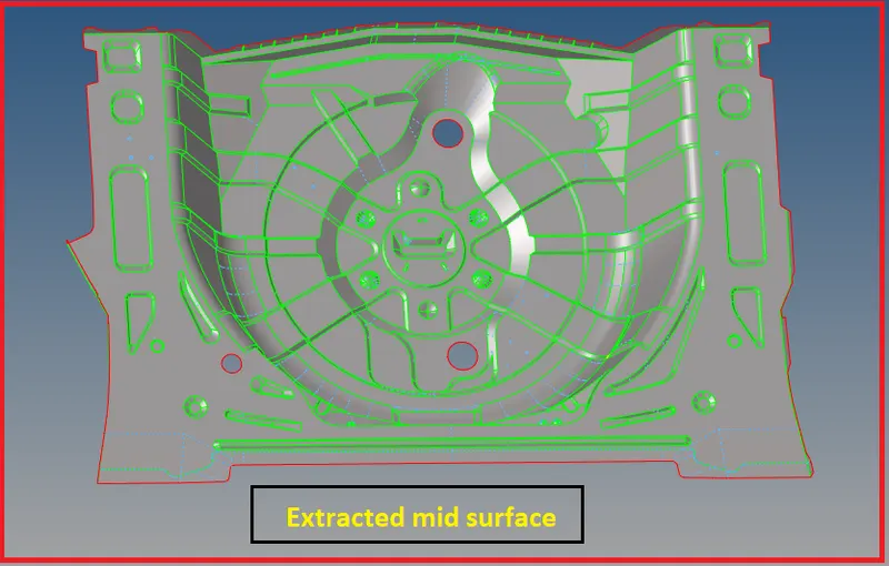
The mid surface created will be assigned to a new collector called Middle Surface.
- Geometric Clean Up on the Mid Surface
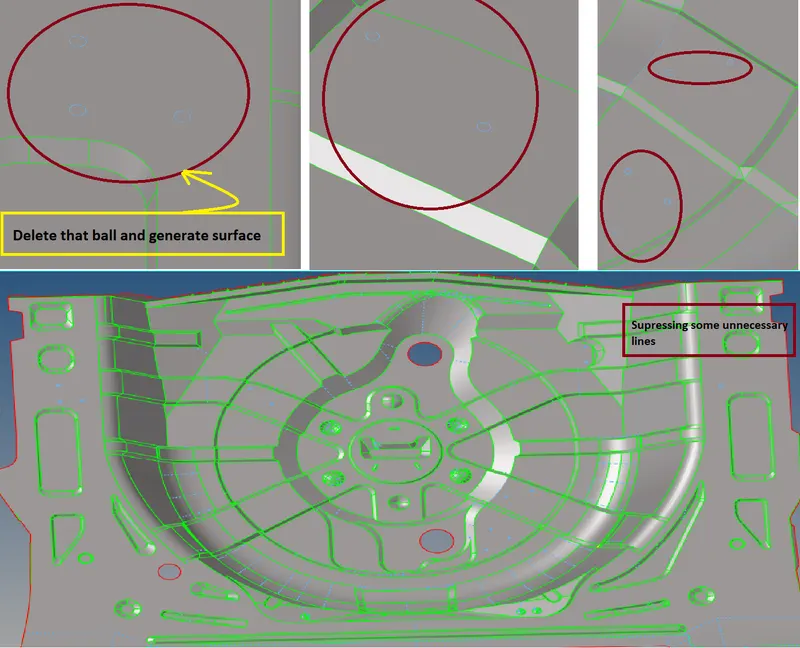
Do a geometric clean up on the mid surface extracted. Check for the free edges in the middle region of mid surface. If there are any free edges, toggle them and eliminate those free edges. Also, we need to fill the gaps (Free Edges) to get a connectivity while meshing.
If we won't fill the gaps, there will be no connectivity while meshing. If we do analysis without filling that gap, Forces won't be distributed in that regions, so fill the gaps and equivalence them.
We can fill the surfaces by using following tools called
- Filler Surface
- Ruled Surface
- Spline
- Skin
- Quality Criteria setting:
Before generating a mesh on the surfaces. Enter the quality criteria given to us in the Challenge.
You can go and enter quality criteria, Command: Tool bar >> preferences >> criteria file settings >> checks for the element criteria >> Enter values >> apply >> ok.
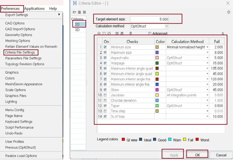
- Aspect Ratio - This is the ratio of the longest edge of an element to either its shortest edge or the shortest distance from a corner node to the opposing edge ("height to closest node").
- Skewness - Skew of triangular elements is calculated by finding the minimum angle between the vector from each node to the opposing mid-side, and the vector between the two adjacent mid-sides at each node of the element. For Skewness: Ideal=0, But < 45 is acceptable.
- Warping - This is the amount by which an element (or in the case of solid elements, an element face) deviates from being planar. Since three points define a plane, this check only applies to quads. The quad is divided into two trias along its diagonal, and the angle between the trias’ normals is measured.
- Taper - Taper ratio for the quadrilateral element is defined by first finding the area of the triangle formed at each corner grid point. These areas are then compared to one half of the area of the quadrilateral.
- Minimum and Maximum Length - The shortest distance from a corner node to its opposing edge (or face, in the case of tetra elements) referred to as height to closest node.
- 2D Meshing
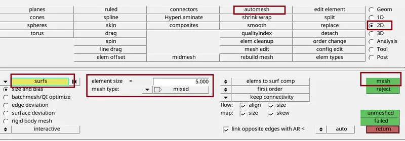
Start meshing from the centre regions or from least free edges. we will get proper mesh density and proper mesh flow. Don't mesh form the edges, It will be difficult and you will get many error, So start meshing from the centre. Choose the element type while meshing. For this component we will be using mixed element type and working on it. We can also quads element type. This type can be used when we have rectangular surface.
Command: 2D >> automesh >> edit the tab as per figure below >> select the surface >> hit mesh >> hit middle mouse click. We can also access this tab by pressing F12 key.
Now start meshing on the surfaces...
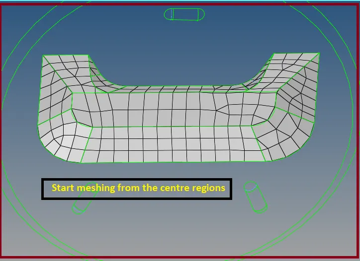
Things need to be ensured while meshing
- Feature Capturing.
- Feature capturing is must while meshing. All the nodes must be connected to the shared edges.
- Tria Management, Avoig higher number of trias.
Important Parameter's in tria management
- No trias in corners or edges.
- No opposite trias.
- No back-to-back trias.
- No trias in fillets or hemming’s (We can have minimum but anyhow try to avoid).
- No rotational quads.
- No trias should share a boundary with feature line.
- Connectivity between elements.
- Split and perform the mesh.
Remesh - Elements are re-meshed with the use of the Hyper Mesh inferred surface algorithm, if geometry for these selected elements needs to exist in the model.
The inferred surface algorithm interpolates geometry data from the selected elements in order to create new mesh.
When elements are selected to be re-meshed, there is the break connectivity option and the vertex angle parameter. The break connectivity option detaches the node connectivity between adjacent selected and unselected elements. This allows you to adjust the node densities along the boundary of the selected elements.
The vertex angle parameter defines the placement of vertices along the boundary of the selected elements. If the angle between two adjacent element edges along the boundaries less the specified angle, a vertex is placed at the meeting point of the two edges.
Anchor nodes create the effect of a fixed point on the inferred surface (which is derived from the existing mesh) and keep the location of the anchor nodes intact.
Rebuild Mesh - It is the process of remeshing existing meshes to generate a new mesh with good quality and flow.
This algorithm saves significant time over the traditional automesh and quality correction approach.
Rebuild is currently supported for first-order 2D meshes that are not attached to 3D element faces.
The rebuild algorithm is useful for many different applications like
1) Remesh to adjust size, quality, and flow.
2) Change to a different element type.
3) Add or remove washer layers around holes, change the nodal density of a hole, adjust a hole diameter, or remove a hole.
4) Locally correct areas with bad mesh flow.
Best way to fix Quality By using Command: 2D >> quality index >> element optimize >> left click on element which are neighbour of quality failing element >> and quality is fix. Here we all option (figure below ) to fix quality.
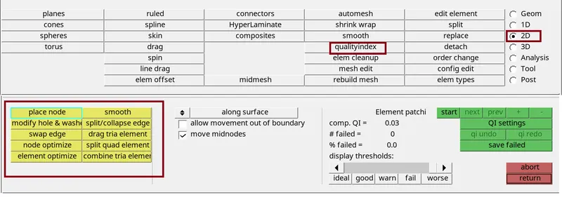
- Place Node - Move the node along the plane or curvature of the surface or away from surface.
- Swap Edge - Each time if we click an edge, it switches to the next valid configuration.
- Element Optimize - To move the mid nodes attached to the element we are optimizing, enabled the with attached mid nodes checkbox.
- Smooth - it is used to improve the element quality of the surface.
- Split/Collapse Edge - To use the split edge tool, left-click on an edge. Hyper Mesh splits the elements that share the selected edge in a way that will achieve the optimum quality.
- Drag Tria Element - To use the drag tria element clean-up tool, left-click on a tria element and drag it to a desired location. Hyper Mesh highlights the selected tria element in pink. Drag both trias to combine when they are facing opposite direction.
- Split Quad Element - To split a quad element, left-click on the quad element you wish to split. Hyper Mesh splits the quad element into two tria elements.
- Combine Tria Element - To combine two tria elements, left-click on their shared edge. Hyper Mesh combines the two tria elements into one quad element.
- Assigning Thickness to the Elements
Steps
a.) Check thickness by distance tool or by dimensioning tool.
- Geometry >> Distance >> Two Points >> Point1,2.
- Geometry >> Dimensioning >> Point1 >> Point 2.
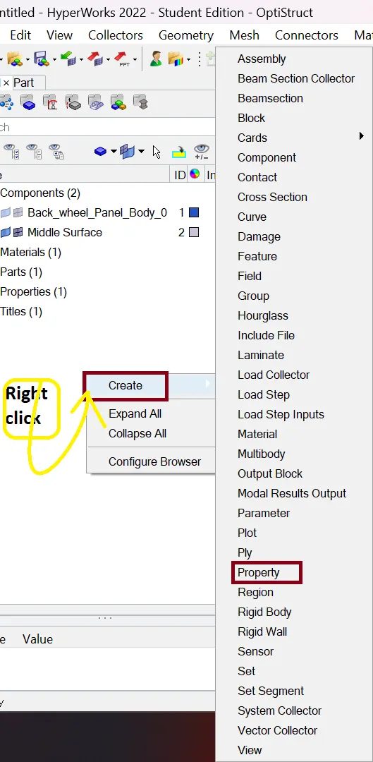
b.) Then Create a property on the browser. To create a property, Right click on browser >> Create >> Property.
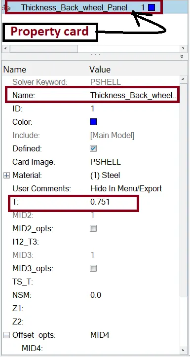
c.) After Creating a property rename it and start assigning thickness to the components.
- Check for Connectivity [Free Edges]:
Command: Tool >> edges >> select the entire element (elems) >> hit find edges
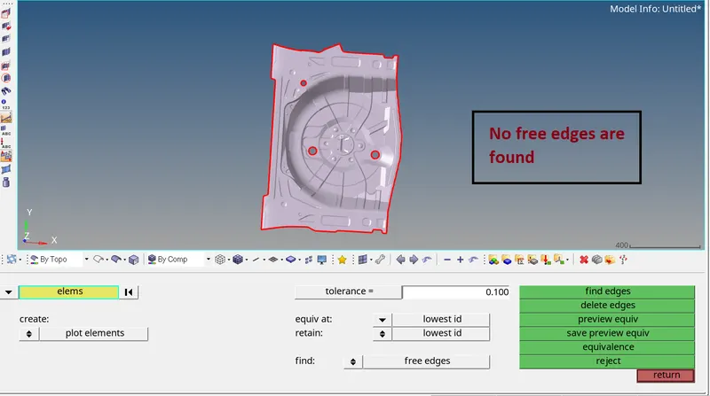
If we get the edges with connectivity, there is no problem, if we get edges without connectivity, then we should have to manually connect them with using replace tool.
- Check for Normals :
Command: Tool >> normals >> select the element >> hit display.
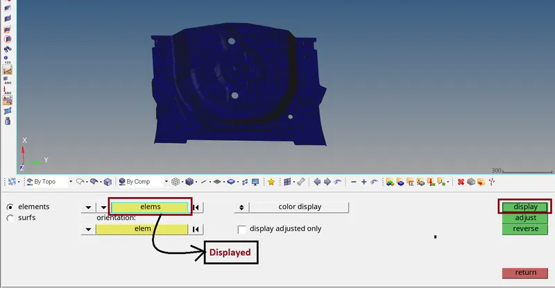
Normals can be reviewed showing a vector or by colors. A vector shows in positive normal direction, while the color mode shows the positive side of a shell or surface in red and the negative side in blue.
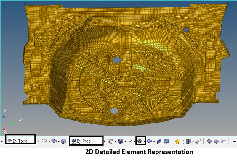
Final Model:
CONCLUSION:
Here the mid surface has been extracted from the parent geometry. there are no surface deformations in the geometry. A well connectivity has been established between the surfaces. The features have been captured properly. A good mesh flow has been achieved with the zero elements failing for quality.
Learning Outcome:
- How to mesh a complex Sheetmetal component.
- How to extract the mid surface manually for the complex Sheetmetal components.
- How to clean complex geometry.
- How to generate a proper mesh flow with low tria percentage.
- How to assign thickness to the components.
*********************************************************************************************************************************************************************************************************************************************************************END
Thanks & regards,