Project 1 - Meshing of Floor Panel
https://drive.google.com/file/d/1Ezf2S-Vj5fgFFHjUtxfJKyQACNmmrwIM/view?usp=share_link please find attached link for your ready references,
Aim: Surface meshing on a floor panel.
Objective:
- To check for the geometrical errors.
- To perform Topology cleanup accordingly.
- to implement meshing according to the required quality criteria.
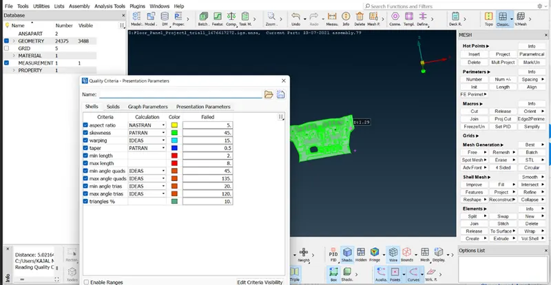
S.No Quality Criteria Value
1 Target/Average length 4
2 Minimum Length 2
3 Maximum Length 6
4 Aspect 3
5 Warpage 15
6 Skewness 45
7 Jacobian 0.7
8 Minimum Quad Angle 45
9 Maximum Quad Angle 135
10 Minimum Tria Angle 30
11 Maximum Tria Angle 120
10 Tria Percentage 15
Procedure
- Importoing the CAD model from the from the desktop page as follow:
Import the model from the file option bar -->new-->select the file from the particular
location.
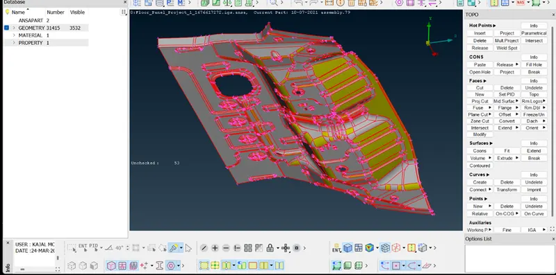
- after importing the CAD model, first and for most need to check the material. This is
done to check the whether the material is defined to model or not. This is done to check
whether the material is defined to model or not.
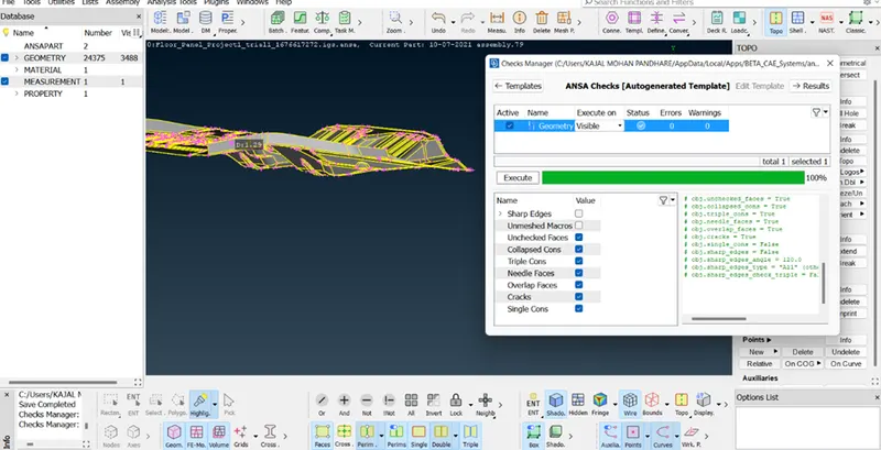
In the similar way find any error in geometry of the particular model as follow. There get
a few geometry error, which is need to be fix. The geometry occurs due to cons in
structure it may be single cons and triple cons. There are some open surfaces that are
generating single cons and it is filled by building surfaces in FACES option.
- Extracting the midsurface: Before extracting the mid-surface for the component, the
thickness of each of the surfaces needs to be known. The thickness of the surfaces can
be measured using the MEASURE command.
By selecting the CONS/Curves option, the distance between two CONS or Curves can
be measured and the thickness value is stored. Similarly, the thickness values are
measured at various places in the CAD model.
The mid-surface for some surfaces can be done using the FACES -> OFFSET.
After extracting the mid surfaces each surfaces has to be assigned a seperate new PID
with respective thickness.
- Batch mesh: After that, we need to assign it a model ID via the model browser.
After creating this new model entry (and naming it), we can move onto the batchmesh
process. On the batch mesh window, we need to go to New > Meshing Scenario. This
creates a batchmesh instance. To achieve that, we must assign a model, which is done
by double-clicking the content for "Meshing Scenario 1" (which would be 0 now). By
doing this, the contents window is opened, allowing us to choose the midsurface
(which I have named "Midsurface"). It is moved from the "pending items" box to the
"meshing scenario" box when it is selected.
Looking at the batchmesh outcomes, it did a respectable job all around.
Unquestionably superior to casting mesh. The few shortcomings of the elements are
simple to remedy. Average, but still superior than the mesh created by casting, is the
flow.
This is the final mesh model where quad element is 94% and tria element is 6%.
Final model:
Conclusion:
The mid-surfaces of the given models are obtained successfully and meshed as per
the mesh parameters and quality criteria. The number of trias and the failed elements
is maintained at a minimum. The models are attached in the below links.
2D meshing on dashboard compoenent
Aim: To create a mid surface and mesh is done by casting with the given quality
criteria and to make sure the element given is free from geometrical errors.
Objective: To perform the geometry cleanup and create a 2-D mesh in the
Dashboard/IP substrate model with the given element quality criteria. After meshing
the component has to be assigned with a thickness.
Quality criteria:
S.No Quality Criteria Value
1Target/Average Length 4
2 Minimum Length 2
3 Maximum Length 6
4 Aspect 3
5 Warpage 15
6 Skewness 45
7 Jacobian 0.7
8 Minimum Quad Angle 45
9 Maximum Quad Angle 135
10 Minimum Tria Angle 30
11 Maximum Tria Angle 120
12 Tria Percentage 15
Procedure:
- Importoing the CAD model from the from the desktop page as follow:
Import the model from the file option bar -->new-->select the file from the particular
location.
We must "prepare" the component in order to make the meshing process easier. This
model needs to be topologically cleaned up. before we can utilise the topo tool from
Faces > Topo in the topo deck. We can move forward after highlighting the entire
component with the tool active. Due to the fact that it is meant to be a closed volume,
this corrects all single cons, which are now accurately represented as double cons.
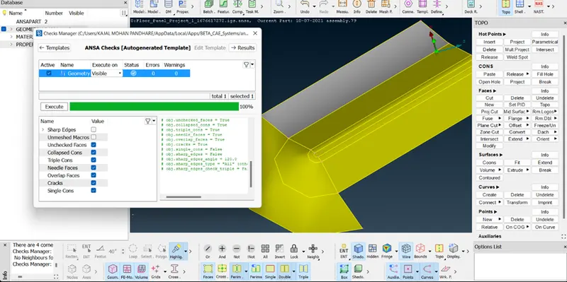
- after importing the CAD model, first and for most need to check the material. This is
done to check the whether the material is defined to model or not. This is done to check
whether the material is defined to model or not.
In the similar way find any error in geometry of the particular model as follow. There get
a few geometry error, which is need to be fix. The geometry occurs due to cons in
structure it may be single cons and triple cons. There are some open surfaces that are
generating single cons and it is filled by building surfaces in FACES option.
- To access to the casting mesh. On the topo deck, select Faces > Mid. Surface >
Casting to go to the casting tool. The casting algorithm then takes over after the
information marked in the following snapshot is entered and entered. It takes some
time to complete.
As we can see, there are a number of pieces that don't meet the required standards for
quality, and the mesh flow isn't all that nice, save for some specific areas.
The casting algorithm appeared to be inaccurate in many areas, particularly when it
came to hole captures and cuts.
Final model:
The Casting was done on the given models and meshed as per the mesh parameters
and quality criteria. The number of trias and the failed elements is maintained at a
minimum. The models are attached in the below links.
2D meshing on switch panel using ANSA
Aim: To create a Mid-Surface and mesh with the given quality criteria and to make
sure the element given is free from geometrical errors.
Objective:
- To check the geometry error
- To perform the topology clean up accordingly
- To implement meshing according to the require quality criteria.
S.No Quality Criteria Value
1 Target/Average length 4
2 Minimum Length 2
3 Maximum Length 6
4 Aspect 3
5 Warpage 15
6 Skewness 45
7 Jacobian 0.7
8 Minimum Quad Angle 45
9 Maximum Quad Angle 135
10 Minimum Tria Angle 30
11 Maximum Tria Angle 120
10 Tria Percentage 15
Procedure:
- Importoing the CAD model from the from the desktop page as follow:
Import the model from the file option bar -->new-->select the file from the particular
location.
- after importing the CAD model, first and for most need to check the material. This is
done to check the whether the material is defined to model or not. This is done to check
whether the material is defined to model or not.
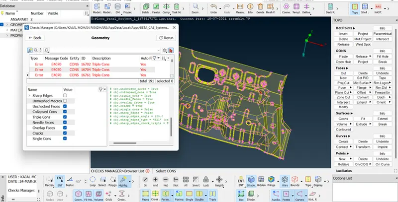
In the similar way find any error in geometry of the particular model as follow. There get
a few geometry error, which is need to be fix. The geometry occurs due to cons in
structure it may be single cons and triple cons. There are some open surfaces that are
generating single cons and it is filled by building surfaces in FACES option.
- Extracting the midsurface: Before extracting the mid-surface for the component, the
thickness of each of the surfaces needs to be known. The thickness of the surfaces can
be measured using the MEASURE command.
By selecting the CONS/Curves option, the distance between two CONS or Curves can
be measured and the thickness value is stored. Similarly, the thickness values are
measured at various places in the CAD model.
The mid-surface for some surfaces can be done using the FACES -
> MIDDLE command. This command generally creates a middle face for the selected
faces. Upon selecting the faces, the confirmation window will pop up. After accepting,
the middle face is created between the two selected faces. This will serve as the mid-
surface for that part. in some places in case of simple structure FACES -> OFFSET.
after extracting the mid surfaces each surfaces has to be assigned a seperate new PID
with respective thickness.
- Meshing the geometry using mesh module
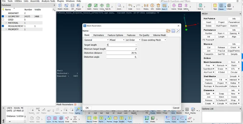
Meshing: mesh length, macros with mesh parameter and mesh quality criteria must be
provided prior to mesh generation but since need to select the entire geometry at once,
need to utilize the same length for all of the geometry. mesh is generated in 1mm size.
setting the mesh parameters as follows as shown in below:
setting the quality parameters as shown:
Best command is used to generate mesh at the sam% and tria element e time Quality
check is performed on the generated mesh. mesh is gernated accordingly such that it
obeys the required quality criteria. Parallelly, mesh clean up is done using the
combination of different commands.
This way the meshing is done for all the surfaces. While meshing, the components need
to be meshed one by one using their PID.
- Error faced: there are many error faced but they were just simple topological errors
and are solved with ease. the main errors are faced while meshing some components.
the error are basically between triple cons of one features to another features. since
ther features arde connected those elements can't be removed are changed.
Conclusion -
Here we can conclude that the bottle cap is successfully meshed after the geometry
topo clean up in FEA software ANSA. Some elements were unable to acquire mesh
quality as per the given quality criteria and failed to gain the feature due to minimum
length, skewness which can be improved at the further stage before final analysis of
the model.