Project 1 - Meshing of Floor Panel
AIM:-
To mesh the given floor panel for the given quality criterias without any failure in the elements.
OBJECTIVE:
- Generate mid-surface manually and perform geometry clean-up on the component.
- Generate mesh with proper mesh flow, with target element size of 5 unit.
- Check the quality of the element according to the given quality criteria.
|
S.No. |
Quality criteria |
Value |
|
1 |
Aspect ratio |
5 |
|
2 |
Skewness |
45 |
|
3 |
Warping |
15 |
|
4 |
Taper |
0.5 |
|
5 |
Min. Length |
2 Unit |
|
6 |
Max. Length |
8 Unit |
|
7 |
Min angle Quad |
45 |
|
8 |
Max angle Quad |
135 |
|
9 |
Min angle Tria |
20 |
|
10 |
Max angle Tria |
120 |
|
11 |
Tria % |
10 |
CAD MODEL :
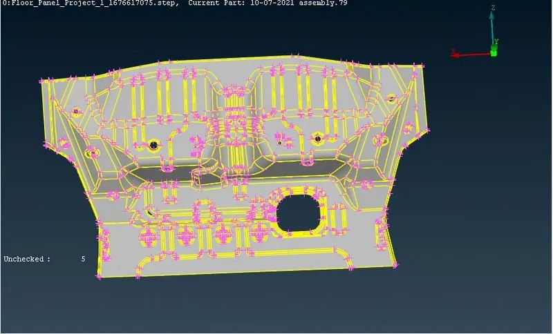
Procedures for Meshing a 2D component:-
i) Importing the CAD model into ANSA:-
The cad model is imported into the Ansa software by clicking File ---> New command.
ii) Geometry Checks:-
Then the important step is to check the geometry of the CAD model. This will helps us to clear all the surface errors, unwanted cons and also for any dissruptions placed in the CAD model.
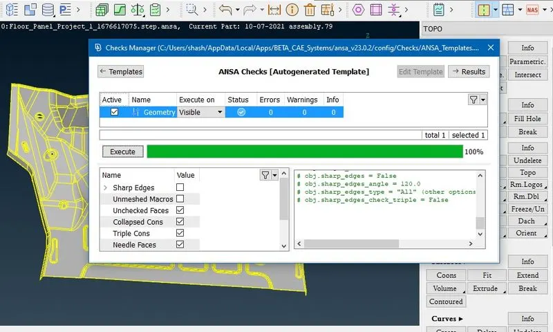
This can be done by giving the command Tools ---> Checks ---> Geometry. And when you check for the geometry, some of the errors will be thrown out by ANSA.
And hence all the CAD models were check for clean geometry and all their surface imperfections are fixed in the geometry check. And once again release all the cons and give Faces ---> Topo.
Then Faces ---> Orient command is used to check the orientation is proper in all the faces of the CAD geometry.
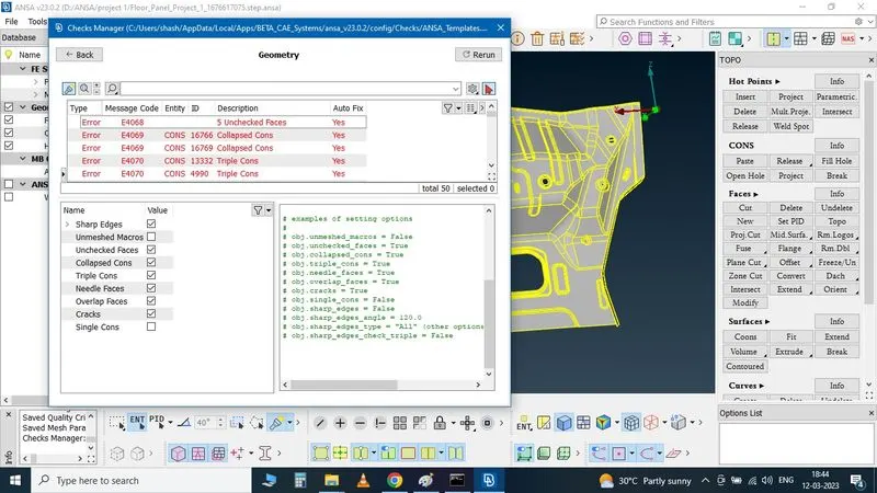
Some of these errors can be automatically resolved by the ANSA by using the command Right click + Fix in the geometry check dialog box. And some of the errors like unchecked faces will be cleared manually using Faces ---> Delete and Faces ---> New commands.
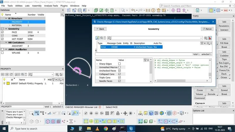
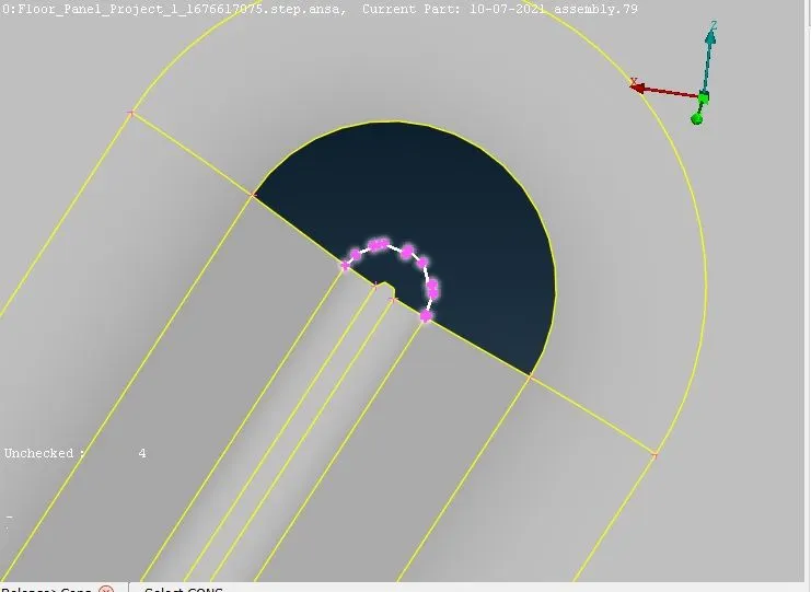
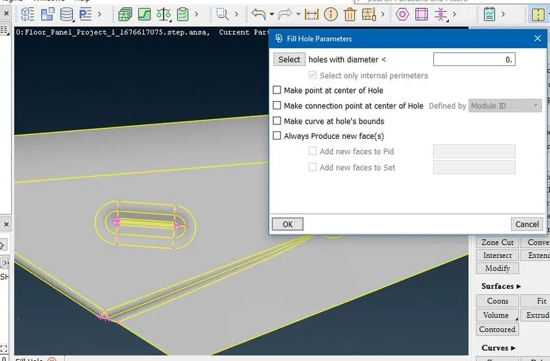
when all of these errors were fixed, the component is again cheched for geometry and is fine to be cleared for all the geometry checks.
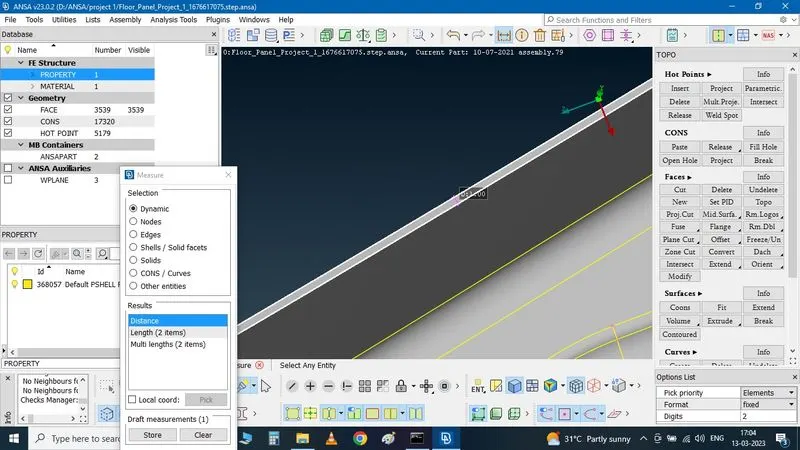
Before extracting the Mid surface of the components, its important to measure their thickness. And this can be achieved by using the command Utilities---> Measure. And by chosing the extreme end of two hotpoints we can get the thickness of the geometry. To double check if the measurement done is correct we measure it in two to three different location.
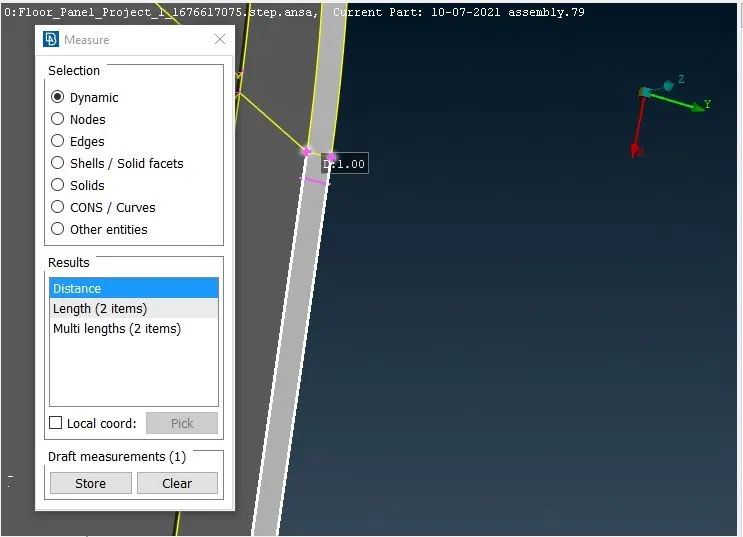
Next, the mid surface is extracted using the Offset tool by going to Faces>Offset and selecting all the surfaces on one face. Then, half of the thickness is given as the offset value, the direction is checked and offset. Now, the property is assigned to the extracted mid surface by going to Faces>Set PID and assigning to the respective property. Similarly, all mid surfaces are extracted and property assigned for all the components.
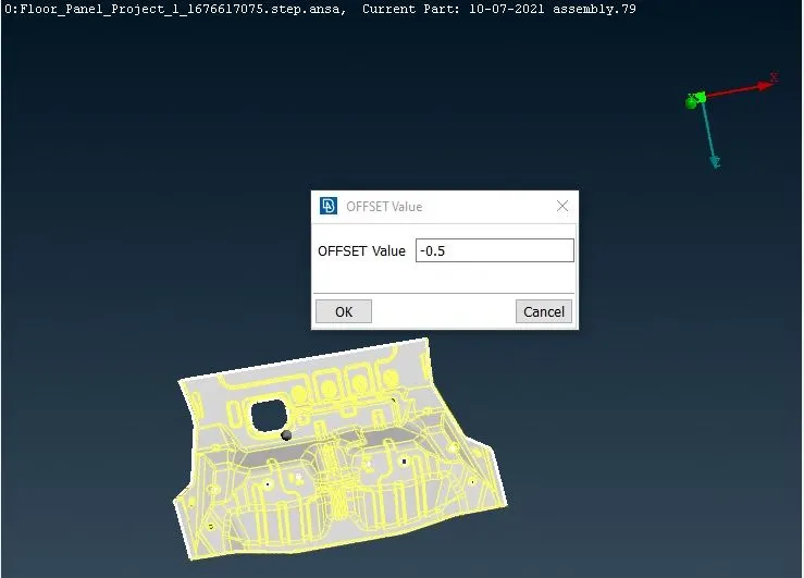
As the Outer panel and Inner panel (except one surface) are symmetrical, only half mid surface is extracted. Similarly, both hinges are mirror images of each other, so the mid surface is extracted for only one hinge.
Again, the extracted mid surfaces are checked for geometric errors and fixed. The final extracted mid surfaces are shown below.
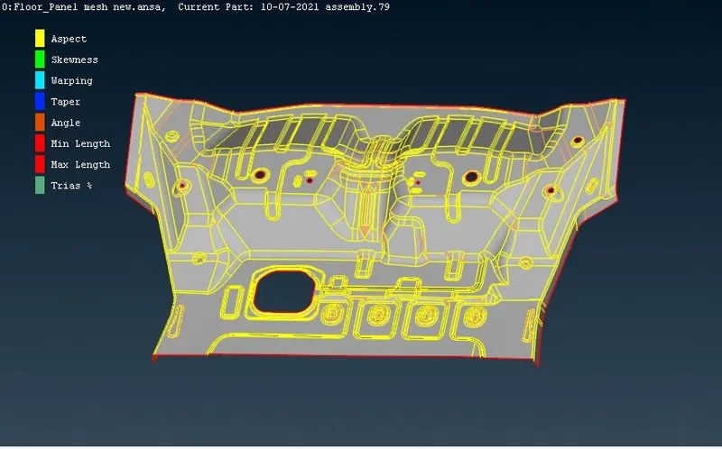
Next, mesh parameters are configured by going to Utilities>Mesh Parameters. There, target length, minimum element length, and maximum element length are configured to 5, 2, & 7, respectively. All other parameters are kept as default for mixed and 1st order elements.
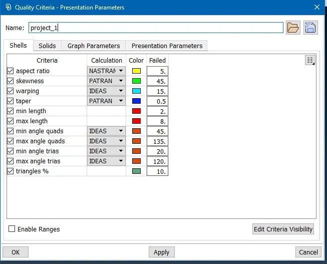
Next, quality criteria are configured by going to Utilities>Quality Criteria. And, the quality criteria file is saved for future reference. The created quality criteria parameters are shown in the image below.
The next step is to prepare the mid surfaces for meshing. For that, switch to the Mesh module. First, the shell element length is altered by going to Perimeters>Length and all the CONS are selected and target element length 5 is fed as length value. The same is done for all the Macros (surfaces).
Next, all the areas are checked for minimum element length and altered where elements might fail for minimum length. Similarly, CONS which are not essential to define a feature are removed by joining the surfaces using the Macros>Join tool. Also, the complete mid surface model is divided strategically into sections using Macros>Cut and Macros>Project Cut tool. This will help to generate a better quality mesh. Also, all the holes are rotated using the Perimeters>Slide tool to ensure the CONS are parallel to the nearby CON. This will help in generating a mesh with good flow. The result of the above steps is shown in the image below. The same process is repeated for all the mid surface components.
Orange CON (edge) represents the joined macros (surfaces) and yellow CON is the new split done to divide the geometry into sections. Also, elements would fail for minimum length in the hemming region. So, for the hemming region, it is split into half along its length and the CON above and below are removed by joining the macros (surfaces).
Next, meshing is done using the Batch meshing tool. This tool generates the mesh using the best algorithm applicable.
Steps to be used in batchmeshing:-
1. After the midsurface is generated we need to assign it a model ID via the model browser (after the midsurface is isolated):
2. After creating this new model entry (and naming it), we can move onto the batchmesh process. The batchmesh tool can be accessed via its namesake in the top toolbar or by pressing Ctrl+B. On the batch mesh window, we need to go to New > Meshing Scenario. This creates a batchmesh instance.
3. Now, this instance needs to work on something. For that, we need to assign a model and that is done by double-clicking the 'Meshing_Scenario_1' content (which would be 0 now). Doing so opens the contents window where we can select the midsurface (Which I named 'Midsurface'). Selecting it moves it from the 'pending items' box to the 'meshing scenario' box.
4. Clicking 'OK' brings us back to the original batchmesh window where we can now have the option to run it. Before doing this, it must be ensured that the quality parameters and criteria have been entered. If they have already been taken care of, we can let ANSA run the batchmesh process.
Then, the created mesh is refined using the Shell Mesh>Reconstruct tool. It is ensured that there are no rotating quads. Also, trias are kept as low as possible. While dealing with trias, the following things need to be ensured.
- No back to back trias touching each other
- No opposite trias
- No trias touching the edges
- No trias on a feature
- Low concentration of trias in a region
To deal with trias, the following tools are used,
- Grid>Paste, to paste the nodes and move tria backward
- Elements>Split, to split an element and move tria forward
- Elements>Swap, to move the tria left or right
- Elements>Join, to join two trias to make a quad
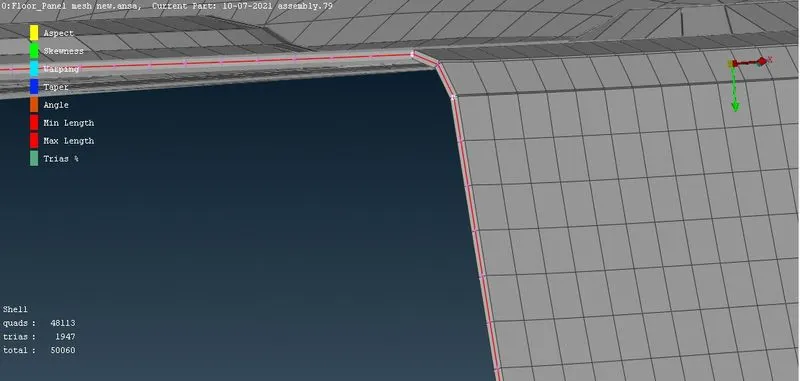
After modifying the mesh, Shell Mesh>Smooth tool is used to smoothen the flow of the mesh. Any elements failing for quality criteria are also fixed by either remeshing or smoothing the elements. The created mesh is shown below,
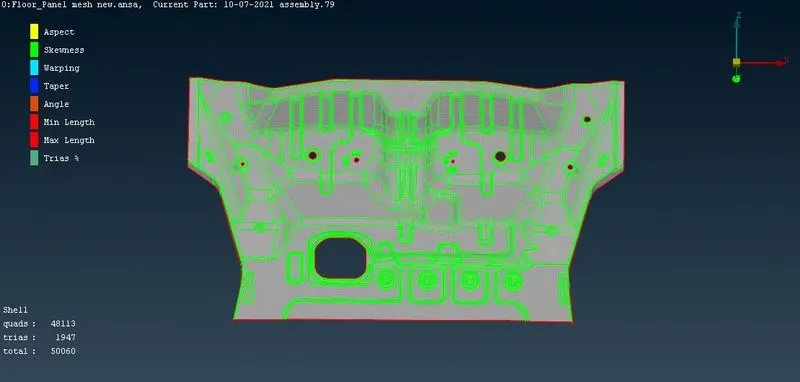
3D representation is turned on in quality criteria --> presentation parameters --> Draw shell as solid
Conclusion:
Geometry cleanup, mid surface extraction, and 2D meshing of the given hood model were successfully done. And all the elements pass the quality criteria. All the features in the model are captured properly with good mesh flow. Tria concentration is kept low.
* NOTE - As the file is more than 100 MB we can zip it to attach for challenge submission.