Project 1 - Meshing of Floor Panel
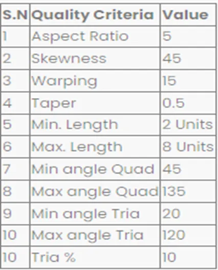
Objective: Mesh the sheet metal component called front panel assign quality parameters as per the given criteria.
Procedure: -
- Checked the geometry connections for the model and executed geometrical checks, fixed the needle faces errors and cracks errors are formed.
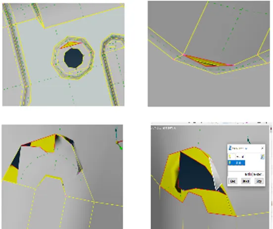
- As shown in above the cracks are formed in the component, those errors were resolved by deleting the faces and created a new face to fill the empty area. Doing that procedure most of the cracks are solved.
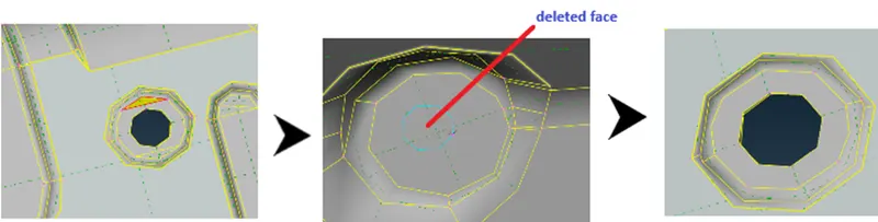
As shown above picture, it is a crack resolved by deleting the face and forming new face where the issue formed. To form a hole project the con to face and delete the unwanted area then we get the original feature.
- The cracks which have gap less than 0.5mm, those errors can be resolved by pasting the cons.
Mid-surface extraction
- Once errors resolved, performed geometrical check then, extracted the mid surface.
- The mid surface taken by a casting approach, it is a method takes the mid surface automatically recognizing the component features and deployed automatic middle mesh on the mid surface.
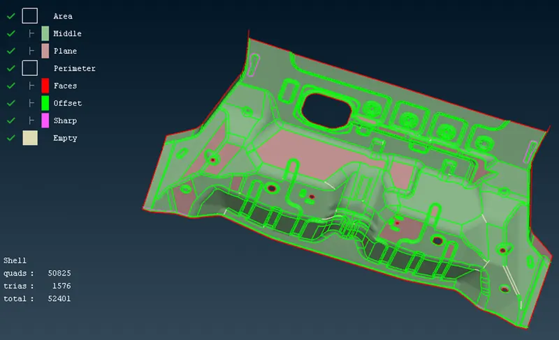
This method gives poor results where the curvature surfaces exists sometimes so, we have to correct the issues with align manager.
The align manager is tool to fix the errors like mis aligned surfaces, irregular geometry, empty cons, perimeters which produces by casting method.
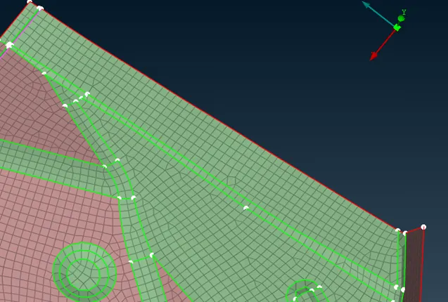
The fillet is reconstructed through the align manager, the cons are become empty perimeter and collapsed so,using align manager, perimeter and imprinted cons onto the mid surface and recreated the curvature boundary.
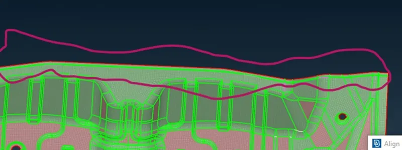
The extra elements are formed due to curvature areas, those where are deleted by elements>delete.
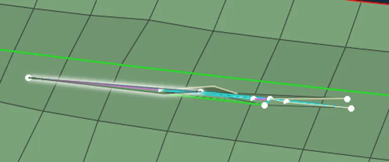
Meshing: -
Casting method gives automatic mesh so, need to perform recreate the mesh flow by using manual methods.
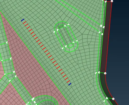
Collapsed trias into shells
- Mesh flow implemented by using techniques like spilt the trias, remove oppsite trias, reconstruction of mesh, freezing the cons into joined cons.
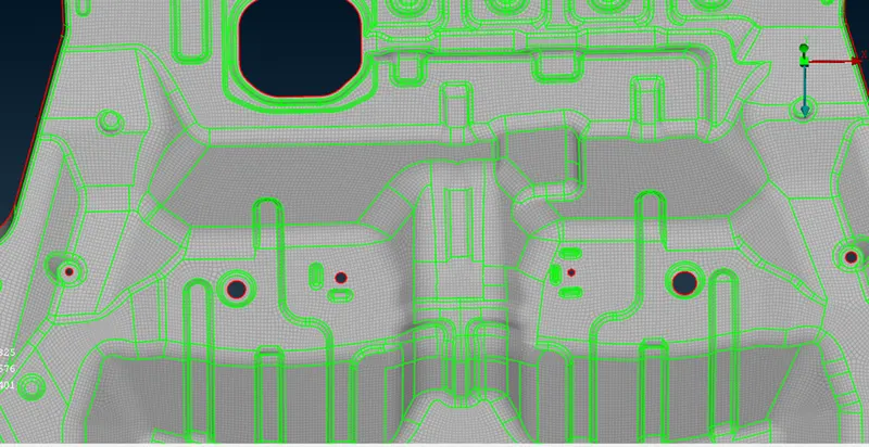
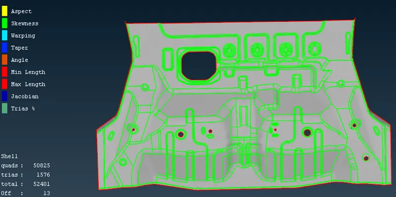
The component has been meshed with in the quality range.
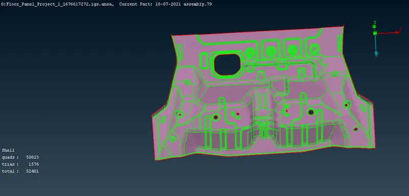
created propertyid for the given componnent and assigned the thickness.
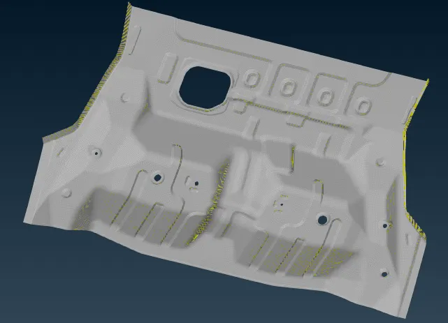
Drawn 2d to 3d solids
Conclusion
The given sheet metal component has been meshed with in the quality range and drawn 2d shells to 3d surface.