Project 1 Mechanical design of battery pack
Battery pack capacity: 18 kWh
Cell: ANR26650M1-B
Prepare a detailed battery pack drawing along with its enclosure. State your assumptions.
Answer:
Abstract:
This detailed analysis outlines the process of designing a battery pack with a capacity of 18 kWh using ANR26650M1-B lithium iron phosphate cells. The study includes calculations for cell volume, energy density, pack configuration, voltage, capacity, energy, volume, and weight. The design also incorporates considerations for cell holders, pack covers, lower floor cases, and positive/negative clips. The final battery pack configuration consists of 50 cells in series and 44 cells in parallel.
Introduction:
The development of a high-performance battery pack is crucial for electric vehicles (EVs) and various other applications. This report delves into the design process for an 18 kWh battery pack using ANR26650M1-B lithium iron phosphate cells. The design takes into account cell specifications, pack configuration, energy requirements, and physical enclosure components.
Cell: ANR26650M1-B specifications
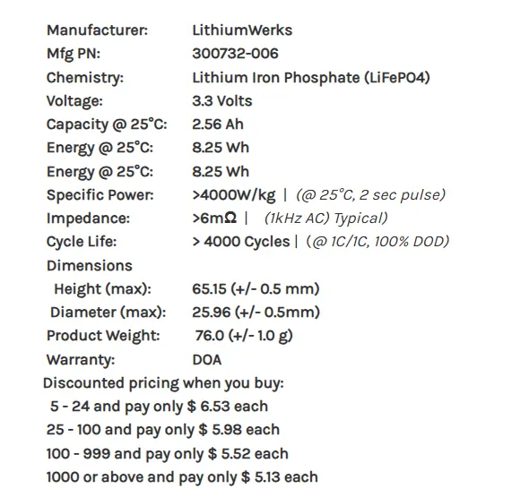
ANR26650M1-B Specifications
Nominal Ratings
Voltage: 3.3 Volts
Capacity: 2.5 Ah
Energy: 8.25 Wh
Specific Power: 2600 W/kg
Impedance (1KHz AC Typical) 6 mΩ
Cycle Life at 1C/1C, 100% DOD: > 4000 cycles
Cell Type: 26650 Lithium Ion Power Cylindrical Cell
Discharging
Max Continuous Discharage: 50 A
Max Pulse Discharge Current >50% SOC (10s): 120 A
Minimum Voltage: 2 Volts
Temperature: -30ºC to 55ºC
Charging
Recommended Standard Charge: 2.5 Amps
Max Charge Rate: 10 Amps
Max Pulse Charge Current <50> Float Voltage: 3.45 Volts
Recommended charge V & Cut-off Current: 3.6 Volts, taper to 125mA
Temperature
(reduce charging current to 250mA when under 0ºC): 0ºC to 55ºC
Mechanical
Diameter: Ø25.96 +/- 0.5 mm (1.0")
Length: 65.15 +/- 0.5 mm (2.6")
Mass: 76 g
Calculation for designing an 18kWh battery pack, basically 18kWh is energy require to achieve the vehicle its proper range. It is depending upon the voltage (V) parameter and ampere-hour or capacity (Ah).
1) To build the Battery pack for any Electric Vehicle, we have to calculate the first proportion of power then motor power, and depend on that we will model the battery pack so we know how much power we required which is 18kWh.
2) For the 18kWh battery Pack we have to calculate how many cells are parallel and how many cells are in series.
3) After calculation of series and parallel combination we have to calculate the proper Geometry and topology consideration for assembling batteries.
4) After Assembly we need to find a proper enclosure for the battery pack for thermal consideration and other physical damages.
The high voltage battery is one of the most important components of a battery electric vehicle (BEV). The battery parameters have a significant influence on other components and attributes of the vehicle, like:
- maximum traction motor torque
- maximum regeneration brake torque
- vehicle range
- vehicle total weight
- vehicle price
A battery cell consists of five major components: electrodes – anode and cathode, separators, terminals, electrolytes, and a case or enclosure. For automotive applications, there are different types of cells used Individual battery cells are grouped into a single mechanical and electrical unit called a battery module. The modules are electrically connected to form a battery pack.
The voltage level of the battery determines the maximum electrical power which can be delivered continuously. Power P [W] is the product between voltage U [V] and current I [A]:
P = U* I
The higher the current, the bigger the diameter of the high voltage wires and the higher the thermal losses. For this reason, the current should be limited to a maximum, and the nominal power obtained by having a higher voltage. For our application, we are going to consider a nominal voltage of 165 V.
Energy needed for propulsion, the high voltage battery must supply the energy for the vehicle’s auxiliary devices Eaux [Wh/km], like 12 V electrical system, heating, cooling, etc. Also, we have to consider the efficiency of the powertrain ηp [-] during the conversion from electrical energy to mechanical energy.
Battery pack architecture:
All high voltage battery packs are made up from battery cells arranged in strings and modules. A battery cell can be regarded as the smallest division of the voltage.
Individual battery cells may be grouped in parallel and/or series as modules. Further, battery modules can be connected in parallel and/or series to create a battery pack. Depending on the battery parameters, there may be several levels of modularity.
The total battery pack voltage is determined by the number of cells in series. For example, the total (string) voltage of 6 cells connected in series will be the sum of their individual voltage.
In order to increase the current capability the battery capacity, more strings have to be connected in parallel. For example, 3 strings connected in parallel will triple the capacity and current capability of the battery pack.
An example is the high voltage battery pack of Tesla Model S, which has:
- 74 cells in a parallel-group
- 6 groups in series for a module
- 16 modules in series
- 7104 cells in total
Battery pack production line:
PROCEDURE:
1) first we have to start with Cell calculation.
2) Then we will do Battery Pack assumptions.
3) After assumptions, we have to do Battery pack calculations.
4) from Cell Dimensions we calculate the surface required for a battery pack.
5) Depending upon the above calculations we build Battery Pack construction.
Cell calculation:
1) Volume of the cell: For the calculation of the volume of the cell we use the formula of Volume of cylinder.
so the formula is: πr2h</math>">πr2h
From Datasheet of Cell, we have 'r' and 'h' values
r=0.013m and h=0.065m = Volume of the cell: πr2h</math>">πr2
: 3.14⋅0.0132⋅0.065</math>">3.14⋅0.0132⋅0.065
:0.0000344929m3</math>">m3m3</math>">
The volume of the cell is 0.0000344929m3</math>">m3
Basically, the value of the volume of the cell is used to find out the total volume of the battery pack.
Cell Energy= Cell Capacity (Ah) × Cell Voltage (V)
= 2.5 × 3.3
= 8.25 Wh
Cell Energy is 8.25 Wh
The value of a single cell is used to calculate the total energy of the battery pack.
Single Cell Energy Density
Volumetric energy (Wh/m3) = Single Cell Energy / Volume of each cell
= 8.25 Wh / 0.0000344929m3
=2,39,179.6572 Wh/m3
Single Cell Energy Density is 2,39,179.6572 Wh/m3
Battery Pack Assumtions:
There are 50 cell are in series and 44 cells are in parallel, and as above maintioned we are going to use Cell: ANR26650M1-B this cells.
Battery pack calculation:
Now we calculated parallel and series combinations so we can now calculate total no of cells required
Total no of cells: Series cells * parallel cells
:50*44
:2200.
Total no of cells required are 2200.
So from series and parallel combination, we can calculate the voltage of battery pack and the current of the battery pack.
Voltage= no of cell in series* nominal voltage.
= 50*3.3
= 165V
The total value of voltage is 165V.
Current=No of parallel cells * cell capacity
= 44*2.5
=110Ah.
The total value of Current is 110Ah
So now we can calculate the how much mount of energy this combination have by product of voltage and current, and check the it will satisfied or not our requirement
Energy= Voltage * Current
= 165 * 110
= 18150WAh
The total value of Energy is 18150WAh.
So our calculation are satisfied requirement what we need.
now we have total no of cells and volume of single cell so we can calculate the total volume required for battery pack
Total volume = no of cells * Volume of single cell
= 2200 * 0.0000344929
=0.07588438m3</math>">m3
Total volume required for battery pack is 0.07588438m3</math>">m3
We also have single cell weight from that we can calculate the total weight of battery pack without other mechanical and electrical connections.
Weight = No of cells * weight of single cell.
= 2200 * 0.076
= 167.2kg
Weight of battery pack is 167.2kg
Energy dencity= volume * battery pack energy
= 0.07588438 * 18150
= 1,377.301497kWh/m^3
Energy dencity is 1,377.301497kWh/m^3
Assembly of the full battery pack with 50s/ 44P. The arrangement of the pack is as follow:
Then,
2112 cells will have 50S / 44P
Here I arrange the pack such that it will build a proper battery pack.
The detail technical specification of 2112 battery pack is as follow:
- Package: 50S / 44P
- Capacity: 110 Ah
- Voltage: 165 V
- Weight: 167.2kg (Only Cells)
- No of Cells: 2100
- Power: 18150Wh or 18.15 kWh
Design of cell holder (Bottom and Top)
The main function of a battery holder is to keep cells fixed in place safely and securely also it is used to keep cells in a proper arrangement so that there will be a decrease in mechanical vibration, and have a better thermal runway in between the cell gaps. Most of the cell holder is made up of polypropylene or nylon bodies rated for 80–100 °C.
Design of pack cover
Basically, Pack cover is made up of Aluminium and the reason behind is to keep battery pack for lightweight. The casing/cover thickness is 0.5 mm and the design is as shown below:
A bottom cover is shown to cover below the bottom battery holder.
Design of Lower floor case for battery pack
Basically, the lower case is a part which is fitted in an electric vehicle for the assembly of the battery pack. A lower case is also made up of aluminum and it has top cover and bottom cover to battery pack from dust and environmental pollution.
Positive and Negative Clip
A positive and negative clip is used to connect the battery end cap i.e (+) and (-). Design is shown below:
To make the battery pack, you have to connect the many cells together by means of Nickel strips or thick wire. Generally, Nickel strips are widely used for this. In general two types of nickel, strips are available in the market: nickel-plated steel strips and pure nickel strips. I will suggest buying a pure nickel. It is a little bit costlier than nickel-plated steel, but it has much lower resistance. Low resistance means, less heat generation during the charging and discharging, which leads to longer useful battery life.
Nickel strips come with different dimensions and lengths.
Joining of Cylindrical Cell Battery Pack
Cylindrical cells have improved thermal management efficiency because of compact shape, but have low packaging efficiency because of their round cross-section. Here I use a positive and negative tab to connect multi cells.
The suitability of joining methods to build battery packs using cylindrical cells is shown below:
Battery Cooling Considerations:
In the design of a high-performance battery pack, thermal management is a critical aspect that must not be overlooked. Proper cooling is essential to maintain the cells within their optimal temperature range, ensuring safety, longevity, and performance. Here, we introduce key considerations for battery cooling in the design.
1. Thermal Management Importance:
Thermal management is vital because temperature extremes can negatively impact battery cells. Excessive heat can reduce cell life, while extreme cold can decrease their efficiency and power output. A well-designed thermal management system maintains the cells within an ideal operating temperature range, typically between 20°C and 40°C for lithium iron phosphate (LiFePO4) cells like the ANR26650M1-B.
2. Cooling Methods:
There are several methods for cooling battery packs:
-
Air Cooling: This is the simplest method, involving the circulation of air around or through the battery pack. It's cost-effective and efficient for moderate temperature control. However, it may not suffice for high-performance applications.
-
Liquid Cooling: Liquid cooling uses a coolant (usually a mix of water and antifreeze) to absorb and dissipate heat. It's highly efficient and allows precise temperature control. Liquid cooling systems often include a pump, radiator, and heat exchanger.
-
Phase Change Material (PCM): PCM is a passive cooling method that utilizes materials that change phase (e.g., from solid to liquid) at a specific temperature. As the material changes phase, it absorbs or releases heat, maintaining a stable temperature.
3. Cooling System Integration:
The chosen cooling method should be integrated into the battery pack's design. This involves the placement of cooling channels, pipes, or fins in proximity to the cells to efficiently dissipate heat. It's crucial to ensure that cooling is uniform across all cells to prevent thermal hotspots.
4. Temperature Sensors:
Temperature sensors should be strategically placed within the battery pack to monitor cell temperatures. These sensors feed data to a Battery Management System (BMS), which can adjust the cooling system as needed to maintain safe temperatures.
5. BMS Integration:
The Battery Management System plays a central role in thermal management. It should be programmed to trigger cooling when temperatures exceed safe thresholds and to balance cell temperatures by controlling the cooling system.
6. Safety Considerations:
Safety is paramount in battery cooling. Proper insulation and sealing are essential to prevent coolant leakage. Additionally, the cooling system should have fail-safe mechanisms to shut down in case of malfunction.
7. Environmental Considerations:
The choice of coolant should consider environmental impact. Many systems use non-toxic, eco-friendly coolants to minimize harm to the environment.
In the design of an 18 kWh battery pack using ANR26650M1-B cells, integrating a robust cooling system is essential to ensure the pack's safety, performance, and longevity. A well-designed thermal management system, whether based on air cooling, liquid cooling, or phase change materials, should be carefully integrated into the overall battery pack design. Proper temperature monitoring, control, and safety mechanisms should be in place to guarantee optimal performance and prevent thermal-related issues. Battery cooling is a critical component that should not be overlooked in the design process.
Safety Considerations:
-
Overcurrent Protection: overcurrent protection mechanisms in place to prevent excessive current flow during charging or discharging.
-
Overvoltage and Undervoltage Protection: battery management system (BMS) ensures that the cells operate within safe voltage limits.
-
Thermal Runaway Mitigation: to detect and prevent thermal runaway, such as thermal fuses or pressure relief mechanisms.
-
Cell Balancing: BMS balances cell voltages to ensure uniform cell performance and prevent overcharging or overdischarging of individual cells.
Charging Infrastructure:
-
Charging Rate: Maximum charging rate the battery pack can handle as per specification and compatibility with common charging standards (e.g., CCS, CHAdeMO, Type 2).
-
Charging Time: Estimate of the time required - 8 hrs to charge the battery pack fully from different charging levels (e.g., from 20% to 80% or from empty to full). 30mins with superfast chargers
Regulatory Compliance:
-
Safety Standards: Ensure that the battery pack complies with relevant safety standards and regulations, such as UN38.3 for transportation and UL 2580 for battery packs.
-
Emissions: Any emissions regulations applicable to the battery pack.
RESULT:
| NO | Calculated Parameters | Value Get |
| 1 |
Cell Volume |
0.0000344929m^2 |
| 2 | Cell Energy | 8.25Wh |
| 3 | Cell Density | 239179.6572kWh/m^2 |
| 4 | Pack assumptions | 50s 44p |
| 5 | Total no of cells | 2200 |
| 6 | Voltage | 165V |
| 7 | Capacity | 110Ah |
| 8 | Energy | 18150WAh |
| 9 | Total volume | 0.07588m^2 |
| 10 | Total Density | 1377.30kWh/m^2 |
| 11 | Weight | 167.2kg |
Conclusion:
The design process for the 18 kWh battery pack using ANR26650M1-B cells has been thoroughly detailed and calculated. Here are the key findings and conclusions based on this information:
-
Cell Analysis: The ANR26650M1-B cells have a nominal voltage of 3.3V, a capacity of 2.5 Ah, and an energy of 8.25 Wh. They exhibit a specific power of 2600 W/kg and an impedance of 6 mΩ. These cells are suitable for building a high-performance battery pack.
-
Pack Configuration: The chosen configuration is 50 cells in series (50S) and 44 cells in parallel (44P). This configuration yields a total of 2200 cells in the battery pack.
-
Electrical Parameters: The calculated voltage for the battery pack is 165V, and the capacity is 110 Ah. The energy stored in the battery pack is 18.15 kWh, meeting the desired 18 kWh capacity.
-
Volume and Weight: The total volume required for the battery pack is approximately 0.07588 m⊃3;, and the weight of the cells alone is 167.2 kg. These values provide essential parameters for designing the physical enclosure of the battery pack.
-
Energy Density: The energy density of the battery pack is calculated to be 1377.30 kWh/m⊃3;, indicating a high energy storage capacity within a given volume.
-
Enclosure Design: The report introduces the design concepts for cell holders, pack covers, lower floor cases, and positive/negative clips, all of which are essential for the physical assembly and protection of the battery pack.
In conclusion, the design process outlined in this report results in a well-configured and high-performance 18 kWh battery pack using ANR26650M1-B cells. Proper attention has been given to electrical and mechanical aspects, ensuring the pack's efficiency, safety, and thermal management. This battery pack is suitable for various applications, including electric vehicles, where high energy density and reliability are paramount.