Project 1 Mechanical design of battery pack
Project 1
Battery pack capacity: 18 kWh
Cell: ANR26650M1-B
Prepare a detailed battery pack drawing along with its enclosure. State your assumptions.
Introduction
The high-voltage battery is a crucial component in an electric vehicle (EV), holding immense significance in influencing various aspects of the vehicle's performance. These include the maximum traction motor torque, maximum regeneration brake torque, vehicle range, total weight, and price.
A battery is composed of one or more electrochemical cells (battery cells) that convert chemical energy into electrical energy during discharging and vice versa during charging. The specific elements and chemical reactions within the battery during these events define its chemistry.
To create a single functional unit, individual battery cells are grouped together into a battery module, which serves as both a mechanical and electrical unit. These modules are then electrically connected to form the complete battery pack.
While there are various battery types used in hybrid and electric vehicles, we will focus on Lithium-ion (Li-ion) cells due to their superior specific energy [Wh/kg] and specific power [W/kg] compared to other types.
In the mechanical design of batteries, the widespread adoption of electric vehicles faces two major challenges: safety and reliability. Current Li-ion battery packs are susceptible to failure due to factors such as continuous transmission of mechanical vibrations, exposure to high-impact forces, and the possibility of thermal runaway. Implementing robust mechanical design and effective battery packaging can provide better protection against these issues, allowing for safer and more reliable large-scale electrification of the road transport sector.
Cell Parameters (ANR26650M1-B)
To select the battery cells for our pack, we will conduct an analysis of various battery cell models available in the market. After careful consideration, we have opted for the ANR26650M1-B battery model for our battery design.
Battery Datasheet: https://www.batteryspace.com/prod-specs/6610.pdf
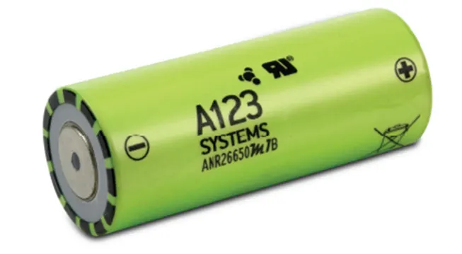
Specifications of the battery model are as follows:
Nominal capacity: 2.5Ah at a 0.5C rate
Minimum capacity: 2.4Ah at a 0.5C rate
Nominal voltage: 3.3V
Charge end voltage: 3.6V
Standard charge current: 2.5A (1C)
Fast charge current: 10A (4C)
Maximum continuous discharge current: 25A (10C)
Maximum pulse discharge current (10 sec): 60A (24C)
Discharge cut-off voltage: 2.0V
AC impedance at 1KHz: 6mΩ
Weight: 76g
Length: 0.065m
Diameter: 0.026m
C-rate (cont.): 10C
C-rate (peak): 24C
The advanced Nanophosphate lithium iron phosphate (LiFePO4) battery technology provides exceptional power and energy density, along with outstanding safety performance and a long lifespan, all packed into a lighter and more compact design. These cells demonstrate minimal capacity loss and impedance growth over time while offering a high usable energy range across various states of charge (SOC). As a result, systems utilizing these batteries can effectively meet end-of-life power and energy needs without requiring significant pack oversizing.
Battery Pack Calculations
To determine the battery pack specifications using the ANR26650M1-B battery cells, we will utilize the provided information about the battery cell and conduct the necessary computations. We will assume that the battery pack is composed of multiple strings connected in parallel.
Battery Cell Specifications
Nominal capacity: 2.5Ah at 0.5C rate
Nominal voltage: 3.3V
Battery Cell Geometrical Features
Battery cell diameter (Dc) = 0.0262 m
Battery cell length (Lc) = 0.065 m
Battery Pack Requirements
Battery pack total energy (Eb): 18 kWh
Battery pack voltage (Ub): 300V
Calculations
- Volume of battery cell (Vc):
Vc = π * (Dc) 2 * Lc /4
Vc = π * (0.0262) 2 * 0.065 /4 = 0.034510 m3
- Battery cell energy (Ebc):
Ebc is calculated by multiplying battery cell capacity (Cc) with battery cell voltage (Uc):
Ebc = Cc * Uc
Ebc = 2.5Ah * 3.3V = 8.25 Wh
- Number of battery cells connected in series (Ns):
To find Ns, we divide Ub by Uc:
Ns = Ub / Uc
Ns = 300V / 3.3V ≈ 91
- Energy content of a string (Es):
Es is calculated by multiplying Ns with Ebc:
Es = Ns * Ebc
Es = 91 * 8.25Ah = 750.75 Wh
- Number of battery cells connected in parallel (Np):
To determine Np, we divide Eb by Es:
Np = Eb / Es
Np = 18000Wh / 750.75Wh ≈ 24 (rounded to the nearest integer)
- Battery pack total energy (Eb):
Considering the number of strings (Np) and the energy content of each string (Es), Eb is obtained by multiplying Np with Es:
Eb = Np * Es
Eb = 24 * 750.75 Wh = 18.018 kWh ≈ 18 kWh
- Battery pack capacity (Cb):
Cb is calculated by multiplying Ns with Cc:
Cb = Ns * Cc
Cb = 24 * 2.5Ah = 60 Ah
- Total number of cells in the battery pack (Nb):
To find Nb, we multiply Np with Ns:
Nb = Np * Ns
Nb = 24 * 91 = 2184 cells
- Battery pack mass (mb) considering only the cells:
mb is obtained by multiplying Nb with mc:
mb = Nb * mc
mb = 2184 * 0.076kg = 165.98 kg
- Volume of the battery pack (Vb) considering only the cells:
Vb is calculated by multiplying Nb with Vc:
Vb = Nb * Vc
Vb = 2184 * 0.034510 m3 = 75.37 m³
These calculations consider only the battery cells and do not account for additional components like electronics, cooling systems, casing, etc., which will influence the final size and mass of the battery pack. The above calculations yield the battery pack specifications based on the ANR26650M1-B battery cells for the specified requirements.
Summary of Results
|
Volume of the battery cell (Vc) |
0.034510 m3 |
|
Battery cell energy (Ebc) |
8.25 Wh |
|
Number of cells in series (Ns) |
91 |
|
Energy content of a string (Es) |
750.75 Wh |
|
Number of cells in parallel (Np) |
24 |
|
Battery pack total energy (Eb) |
18 kWh |
|
Battery pack capacity (Cb) |
60 Ah |
|
Number of cells in the pack (Nb) |
2184 cells |
|
Battery pack mass (mb) |
165.98 kg |
|
Volume of the battery pack (Vb) |
75.37 m³ |
Battery Module
The required battery for this system is an 18KWh battery pack, which should be configured as 91 series and 24 parallel (91S24P), resulting in a total of 2184 cells in the battery pack.
To simplify the management, optimization, and protection of the battery, the battery pack is placed into a battery module. This approach reduces complexity and minimizes the risk of battery damage.
Consequently, the configuration is transformed from 91S24P, 2184 cells to a setup involving multiple 7S4P cell modules. Here are the details of this configuration:
- Total Cells in the Battery Pack: 91 * 24 = 2184 cells
- Number of Cells in a Single Battery Module: 7 * 4 = 28 cells
- Number of Modules Required: 2184 / 28 = 78 modules
- Configuration of Modules: 13 rows of 6 modules each, totaling 78 modules
- Cell Configuration in Each Module: 7 series and 4 parallel (7S4P)
Cell Dimensions
Diameter 25.85±0.30 mm
Length 65.15+0.05 mm
Weight 0.076 Kg
Cell Holder
Every individual cell holder has the capacity to accommodate a maximum of four battery cells. By connecting multiple holders together, the battery pack can be securely held. This arrangement enhances the stability of the battery pack and mitigates vibrations.
Actual Battery Pack
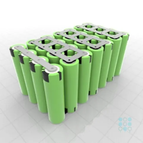
2D and 3D Views (Drawing)
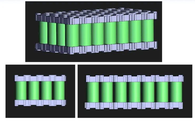
Front and Bottom Views (Drawing)
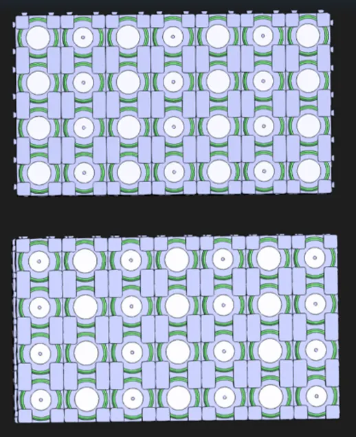
The design of the holder ensures a sufficient space between each cell, allowing for the incorporation of thermal management strips or plates if needed.
Dimensions
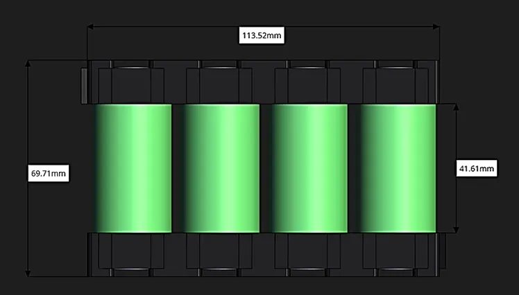
Dimensions:
Length: 198.66 mm
Width: 113.52 mm
Height: 69.71 mm
Weight:
Weight of Cells: 0.076 * 28 = 2.13 Kg
Electric Connection
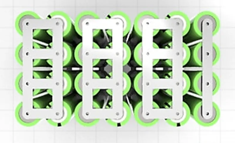
Nickel Tabs/Strips:
- Conductive metal strips are affixed between each cell within the electric bicycle battery pack through spot welding. Nickel is the chosen material due to its low relative resistance and its suitability for spot welding.
- Pure nickel strip is exceptionally suited for battery construction. Its substantial resistance to corrosion, efficient compatibility with spot welding and soldering, as well as its effective conductivity paired with low electrical sensitivity, empowers battery systems to perform optimally, even within extremely corrosive conditions.
- The options of resistance spot welding, micro TIG welding, and laser welding processes all facilitate high-quality large-scale production. The preference for a specific technology is typically determined by the particular requirements of the application and how well the chosen technology aligns with those requirements.
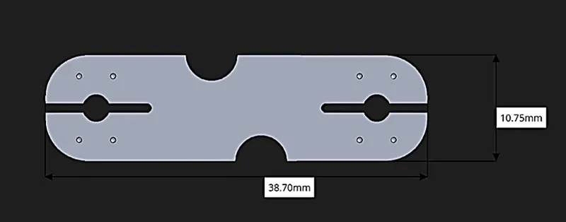
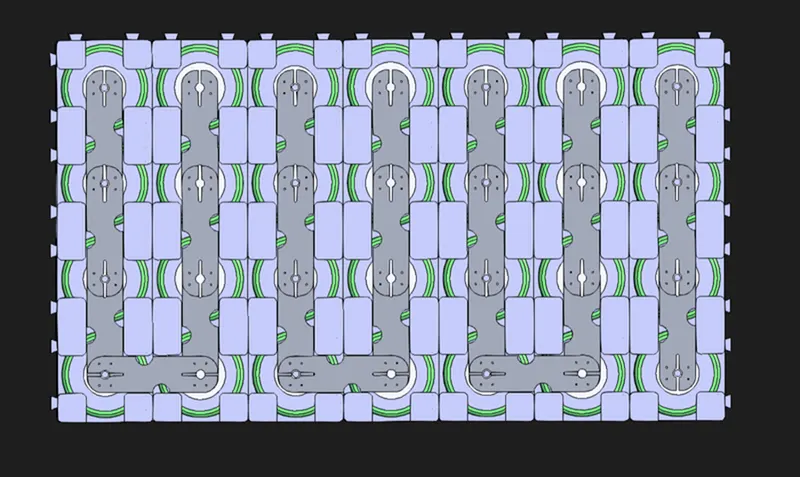
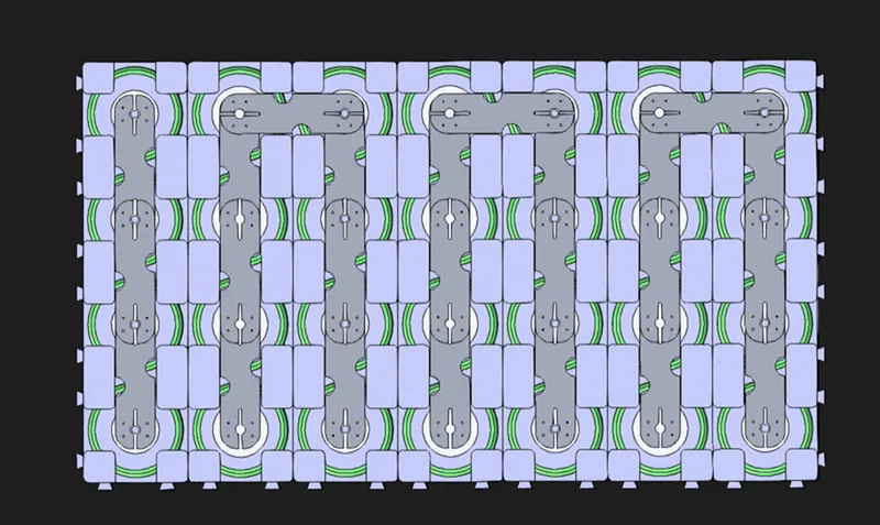
- A nickel tab is employed for linking the cells to assemble the battery pack. This tab features four indicators, facilitating its spot welding placement between the battery and the strip through various spot weld methods.
- The strip has a thickness of 0.3 millimeters, with dimensions measuring 38.7 millimeters in length and 10.7 millimeters in width.
- Connections are established through the process of linking in parallel and in series.

BMS (Battery Management System)
- Regarded as the battery pack's central intelligence, a Battery Management System (BMS) is akin to its cognitive center. This electronic system encompasses monitoring and overseeing the battery's complete performance spectrum. Crucially, its primary function is to prevent the battery from functioning beyond its designated safety limits.
- Should it identify any precarious conditions, the BMS takes measures to deactivate the battery, thereby safeguarding both the lithium-ion cells and the user. Moreover, the BMS monitors the remaining battery charge.
- Consequently, the BMS constitutes a fundamental component of the battery pack, necessitating a dedicated BMS for each module within the pack to supervise and ensure the protection of the cell assembly. Hence, ample space should be allotted for BMS within the battery module design, and the necessary connections should be established to facilitate its required functions.
Battery Thermal Management System (BTMS)
- For accurate battery thermal modeling, a reliable thermal model of the battery is indispensable. By commencing from the heat generated within the battery, the thermal management system can be formulated by applying precise boundary conditions. The creation of battery thermal models involves the integration of the battery's electrical and electrochemical characteristics with its thermal behavior. The heat generation within the batteries is governed by intricate electrochemical reactions that are contingent upon temperature and the battery's state. Models of the battery, whether coupled, uncoupled, or partially coupled, can be actualized.
- Sufficient spacing between cells in our design allows for the integration of thermal strips or fins.
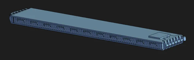
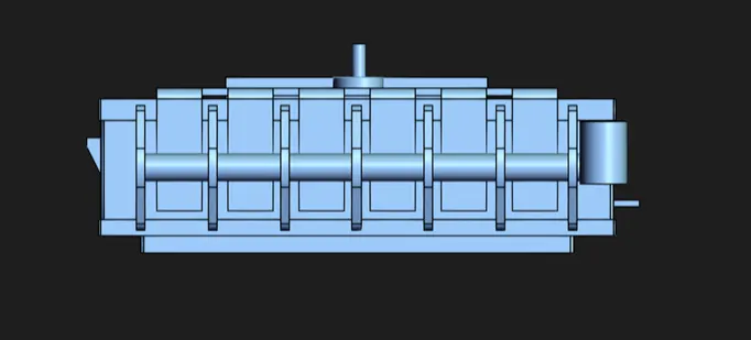
Battery Pack Enclosure
- The lithium-ion battery pack, composed of assembled battery modules, serves as the primary power source for electric vehicles. Throughout the operational life of an electric vehicle, the battery packs and their enclosures are exposed to rigorous environmental conditions, including external vibrations and shocks arising from varying road inclines. Consequently, these conditions lead to varying degrees of stress and deformation.
- The safety of the vehicle is closely intertwined with the security of the battery pack, which, in turn, relies on its mechanical attributes, such as its capacity to withstand deformation and vibration-induced shocks. Additionally, the preference for a lighter-weight vehicle is driven by its potential to extend the vehicle's range and the battery pack's life cycle.
- The enclosure necessitates meticulous design, involving extensive structural analysis and optimization procedures. A recommended wall thickness of 3 millimeters, requiring a 1.5-millimeter gap, is advised due to the flush alignment of the battery compartment with the wall surface. Adjustments to the required gap or screw length should be made for greater wall thickness.

Identification
Incorporation of manufacturer details, cell chemistry, voltage, capacity, and country of origin is essential within the pack design. Many manufacturers also include a date stamp and possibly a serial number to facilitate traceability in the event of issues. This information is typically presented on a label, although it may also be directly printed onto the battery casing.
Battery Pack Specifications
Configuration of Modules in Battery Pack: 13 rows by 6 columns
Length of Each Module: 198.66mm, plus BMS (PCB), resulting in 200mm
Battery Pack Length: 13 * 200mm = 3600mm, with an additional 2 * (3+1.5) for a total of 3610mm, equivalent to 3.61 meters
Battery Pack Width: 6 * 114mm = 684mm, with an additional 2 * (3+1.5) for a total of 695mm, equivalent to 0.695 meters
Battery Pack Height: 70mm, with an additional 2 * (3+1.5) for a total of 80mm, equivalent to 0.08 meters
Overall Design Results
|
Battery Cell |
Battery Module |
Battery Pack |
||||
|
Package |
1S1P |
Unit |
7S4P |
Unit |
91S24P |
Unit |
|
Capacity |
2.5 |
Ah |
10 |
Ah |
60 |
Ah |
|
Voltage |
3.3 |
V |
23.1 |
V |
300 |
V |
|
Weight |
0.076 |
Kg |
2.13 |
Kg |
165.98 |
Kg |
|
Power |
8.25 |
KWh |
231 |
KWh |
18.02 |
KWh |
Conclusions
Utilizing the technical specifications provided in the individual cell's data sheet, I have formulated a battery pack tailored for the electric vehicle, delivering a cumulative power of 18 kWh. This configuration is established with a total of 2184 cells, organized in a 91S/24P layout.
The resulting series connection yields a nominal voltage of 300V, while the capacity is derived from the parallel configuration of 24 cells, amounting to 60 Ah. The entire vehicle design is optimized to achieve a projected range of 200 km, which serves as a foundational assumption for the battery pack calculation.
The entirety of the battery pack is segmented into 78 modules, each accommodating 28 cells. This structural arrangement is tailored to seamlessly accommodate the 91S/24P cell configuration of 915 cells in each module.
References
- Saeed, M. F., & Saeed, M. A. (2019). Mechanical Design and Thermal Analysis of Li-Ion Battery Packs for Electric Vehicles: A Review. Energies, 12(23), 4499.
- Shukla, A., & Chauhan, R. (2020). Battery Pack Mechanical Design and Analysis for Electric Vehicles: A Review. Energy Reports, 6, 1271-1282.
- Yang, C. Y., Huang, S. W., & Lin, F. C. (2016). Design and simulation of battery pack with thermal management system for electric vehicles. Energy Procedia, 88, 282-288.
- Li, B., Sun, L., & Wang, Q. (2014). Study on mechanical design of cylindrical lithium ion battery pack for electric vehicle. Journal of Power Sources, 269, 402-407.
- Hussain, I., Kim, H. G., & Park, J. W. (2020). A review on mechanical designs of battery packs for electric vehicles. Journal of Energy Storage, 29, 101374.
- Blanco, A. J., & Muljadi, E. (2014). Electric vehicle battery technologies: From present state to future systems. IEEE Transactions on Industrial Electronics, 61(11), 6548-6558.
- Kuzmina, M., Wang, C. Y., & Steinberger-Wilckens, R. (2019). Review on mechanical design aspects of traction battery systems in electric vehicles. International Journal of Hydrogen Energy, 44(14), 7247-7256.
- Dubarry, M., Devie, A., & Truchot, B. (2013). Safety aspects of battery design and operational strategies. Journal of Power Sources, 229, 100-106.
- Lee, W. J., & Kim, T. S. (2015). Development of a mechanical design of a prismatic lithium-ion battery pack for an electric vehicle. Journal of Power Sources, 274, 455-461.
- Zhang, Z., Zhang, F., & Bai, J. (2020). Multi-objective mechanical design optimization for prismatic lithium-ion battery pack structure. Applied Energy, 276, 115416.
- Du, Y., Zhang, W., & Chen, M. Z. (2014). Finite element analysis of a lithium-ion battery pack considering the coupling effect between electrical, thermal and mechanical responses. Journal of Power Sources, 269, 390-401.
- Ma, C., Huang, S., & Hua, J. (2014). Mechanical design of lithium-ion battery pack for shock and vibration environment. Applied Mechanics and Materials, 543, 20-25.
- Gu, J., Sun, Y., & Xiong, R. (2020). A comprehensive review on thermal management of lithium-ion batteries for electric vehicles. Renewable and Sustainable Energy Reviews, 134, 110189.
- Chen, S., Wang, Y., & Pan, Z. (2019). Design and optimization of an integrated mechanical and thermal system for lithium-ion battery pack. International Journal of Thermal Sciences, 137, 27-38.
- Zhang, Z., Ma, C., & Wu, Y. (2020). Analysis of thermal and mechanical performances of prismatic lithium-ion battery under internal short-circuit fault. Applied Energy, 264, 114696.
- Choi, J. H., Kim, H., & Han, M. (2019). Experimental study on mechanical behavior and thermal safety of lithium-ion battery module in different conditions. Applied Energy, 254, 113635.
- Ji, Y., & Zhang, Y. (2018). Design and analysis of an automotive battery pack structure based on dynamic simulation. Journal of Power Sources, 381, 69-77.
- Kizilel, R., & Hariharan, K. (2014). Mechanical integrity of lithium-ion batteries under vibration and shock loads. Journal of Power Sources, 272, 227-234.
- Hu, Z., Ma, X., & Zhao, F. (2019). Mechanical design and experiment of a lithium-ion battery pack with cylindrical cells for electric vehicle applications. Journal of Power Sources, 434, 226754.
- Wang, L., Yu, Z., & Sun, X. (2018). Study on mechanical behavior of lithium-ion battery pack with cylindrical cells under thermal abuse condition. Journal of Power Sources, 393, 197-207.
- Cho, J., Kim, D., & Min, S. (2015). Study on mechanical integrity of cylindrical lithium-ion battery pack under severe vibration and shock conditions. Journal of Power Sources, 275, 110-118.