Project 1 Mechanical design of battery pack
AIM:
The aim of the project is to prepare a detailed battery pack drawing along with its enclosure. The capacity of the battery pack we have to prepare battery pack drawing is of 18 kWh. The cell to be used for the battery pack is ANR26650M1-B.
Introduction:
As electric vehicles are increasing in the market is gradually increasing, there is considerable growth in the production of lithium-ion batteries, as it is the electrical source for the electric vehicle (EV). A lithium-ion battery is a type of rechargeable battery in which lithium ions move from the negative electrodes through an electrolyte to the positive electrode during discharge and back when charging. Lithium-ion batteries use an intercalated lithium compound as the material at the positive electrode and typically graphite at the negative electrode. Lithium-ion batteries are made use of various different electrodes. The most common material use is lithium cobalt oxide and graphite which are most commonly found in portable electronic devices such as cellphones and laptops. LIthium manganese oxide and lithium iron phosphate are also used as cathode materials.
Internal Structure of Lithium-ion Battery:
A battery is made up of an anode, cathode, separator, electrolyte and two current collectors. The anode and cathode store the lithium. In general, the cathode material is composed of cobalt-base, nickel-base or manganese-base transition metal oxides and anode material is composed of graphite. The electrolyte carries positively charged lithium ions from the anode to the cathode and vice versa through the separator. The movement of the lithium ions creates free electrons in the anode which creates a charge at the positive current collector. The electrical current then flows from the current collector through a device being powered (cell phone, computer, etc.) to the negative current collector. The separator blocks the flow of electrons inside the battery. Both cathode and anode are manufactured using a layered structure and the lithium ions are located in between layers. During charge, the lithium ions move from the cathode to the anode. During discharge, the lithium ions move from anode to the cathode. Figure (1) shows the basic structure of lithium-ion battery.
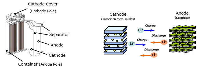
Figure (1): Basic structure of Lithium-ion Battery
There are several types of batteries used in hybrid and electric vehicle propulsion systems but we are going to consider only lithium-ion cells. The main reason is that lithium-ion batteries have higher specific energy (Wh/kg) and specific power (W/kg) compared with other types. The following plot shows the Ragone chart of different cells. The lithium-ion shows its best characteristics compared to other cells. Figure (2) shows the Ragone chart for different types of cells.
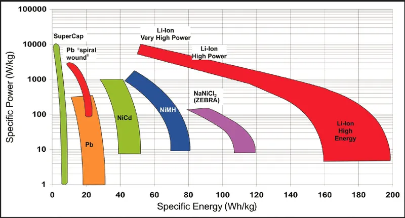
Figure (2): Ragone Plot
ANR26650M1-B:
A123's high performance Nanophosphate lithium iron phosphate (LiFePO4) battery technology delivers high power and energy density combined with excellent safety performance and extensive life cycling in a lighter weight, more compact package. The cells have low capacity loss and impedance growth over time as well as high usable energy over a wide state of charge (SOC) range allowing their systems to meet end of life power and energy requirements with minimal pack oversizing. Nanophosphate battery technology offers thermal stable chemistry, faster charging, consistent output, low capacity loss over time and superior total cost of ownership. It provides the foundation for safe systems while meeting the most demanding customer requirements. Multiple layers of protection are employed at the chemistry, cell and system level to achieve an energy storage solution with superior safety and abuse tolerance compared to metal oxide lithium-ion chemistries. Figure (3) shows the Nanophosphate high power Lithium ion cell ANR26650M1-B.
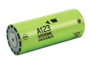
Figure (3): Nanophosphate Lithium-ion Cell ANR26650M1-B by A123 Systems.
The following table below is the technical data of ANR26650M1-B cell of A123 System.
| Parameters | Data |
| Cell Dimension | `phi`26x65mm |
| Cell Weight | 76g |
| Cell Capacity (Nominal/Minimum) at 0.5C Rate | 2.5/2.4Ah |
| Voltage (Nominal) | 3.3V |
| Internal Impedance (1kHz AC typical) | 6m`ohm` |
| Power | 2600W/kg |
| Recommended Standard Charge Method | 2.5A to 3.6V CCCV, 60min |
| Recommended Fast Charge Method to 80% SOC | 10A to 3.6V CC, 12min |
| Maximum Continuous Discharge | 50A |
| Maximum Pulse Discharge (10 seconds) | 120A |
| Cycle life at 20A Discharge, 100% DOD | >1000 cycles |
| Operating Temperature | -30degC to 55degC |
| Storage Temperature | -40degC to 60degC |
From the above specification, the nominal voltage is 3.3V and the cell capacity is 2.5Ah. If we observe the characteristics of the ANR26650M1-B by different conditions like constant power discharge characteristics, constant current discharge at various temperatures are as shown below in figure (4) and figure (5) respectively.
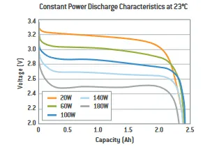
Figure (4): Constant Power Discharge Characteristics at 23 Deg C.
As per the characteristic above, it is clear that is by increasing the power at constant temperature it decreases the voltage respectively.
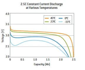
Figure (5): 2.5C Constant current discharge at various temperatures.
Here, when the temperature is reduced from 45 Deg C, it is observed that there is a dip in the battery voltage in the beginning of the discharge cycle at constant discharge current 2.5C rate. If we observe the characteristic of 2.5C rate constant current discharge curve, there is a sharp dip in the battery voltage and the battery capacity is also reduced almost to 2.2Ah than the nominal capacity which is 2.5Ah.
The cycle performance, 100% DOD, various temperatures and discharge rates characteristics of ANR26650M1-B is shown in figure (6) below.
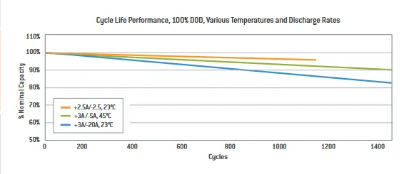
Figure (6): Cycle Life Performance, 100% DOD, Various Temperatures and Discharge Rates Characteristics of ANR26650M1-B.
In this characteristic, we can observe that by changing the charging and discharging cases as shown its performance characteristics changed, here (+) represents charging and (-) represents discharging. While charging, the temperatures and its performance change.
Dimension of ANR26650M1-B cell:
The design of ANR26650M1-B cell with dimensions are shown below in figure (7).
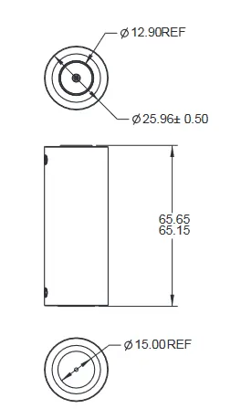
Figure (7): Mechanical Dimension of ANR26650M1-B.
As we know that the safety, designing, sizing and some other things are more important to any of the object they play the key role for the transport, manufacturing, etc. If we see these aspects in the lithium-ion cell batteries it is difficult to transport the battery because of the vibrations, exposure of high impact of the forces and thermal runaway. To avoid all these to small the robust mechanical designs are necessary. Here the mechanical designs play a major role before using in the vehicles or some other machines because if any problem occur in the designing time it leads to damage the battery or creates a major problem in the circuit. In designing battery packing provide a greater degree of protection.
Battery Pack:
As we all know that a battery pack is a set of any number of (preferably) identical batteries or individual battery cells. They may be configured in series, parallel or combination of both to deliver the desired voltage, capacity or power density. The term battery pack is often used in reference to cordless tools, radio controlled hobby toys and battery electric vehicles (EVs). Compoonents of battery packs include the individual batteries or cells and the interconnects which provide electrical conductivity between them. Rechargeable battery packs often contain a temperature sensor which the battery charger uses to detect the end of charging. Battery regulators are sometimes used to keep the voltage of each individual cell below its maximum vaule during charging sa as to allow the weaker batteries to become fully charged, bringing the whole pack into balance. Active balancing can also be perfomed by battery balancer devices which can shuttle energy from strong cells to weaker cells in real time for better balance. A well balanced pack lasts longer and delivers better performance. Many times, the physical configuration makes it more attractive to use many small cells rather than a few large cells, since a large block is harder to fit than several small subunits. Figure (8.1) and (8.2) shows the typical battery pack of electric vehicle.
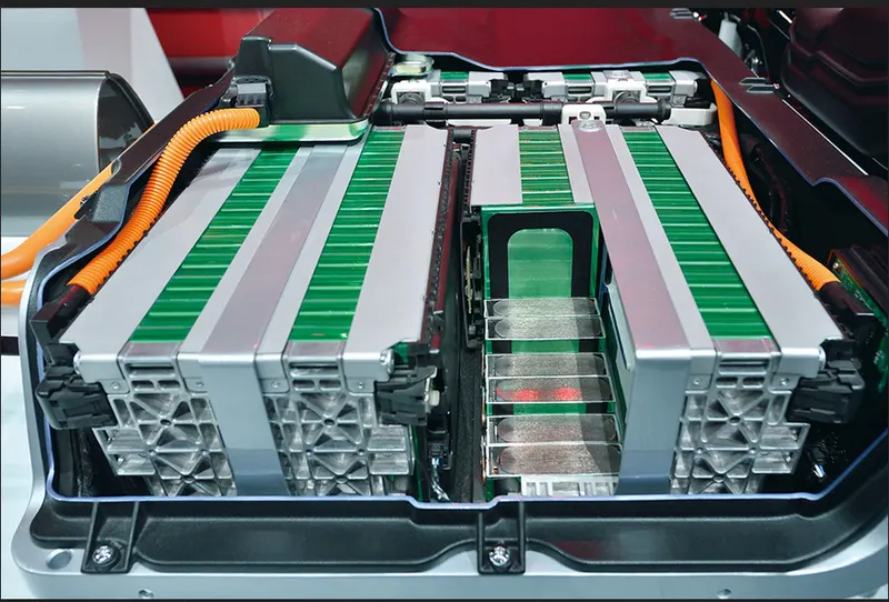
Figure (8.1): Battery Pack used in EV.
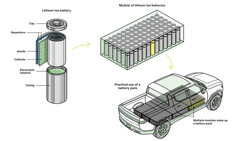
Figure (8.2): Lithium-ion battery pack module used in EV.
Advantages:
An advantage of a battery pack is the ease with which it can be swapped into or out of a device. This allows multiple packs to deliver extended runtimes, freeing up the device for continued use while charging the removed pack separately. An advantage of a battery pack is the ease with which it can be swapped into or out of a device. This allows multiple packs to deliver extended runtimes, freeing up the device for continued use while charging the removed pack separately.
Disadvantages:
Packs are often simpler for end-users to repair or tamper with than a sealed non-serviceable battery or cell. Though some might consider this an advantage it is important to take safety precautions when servicing a battery pack as they pose a danger as potential chemical, electrical and fire risks.
Battery Pack Designing:
The following are the desired characteristics of a battery pack:
1) Light Weight.
2) Long-lasting.
3) Optimum Cost.
4) Waterproof.
For electric vehicle battery design, we should start from the following core input parameters:
1) Chemistry.
2) Voltage.
3) Average energy consumption of the vehicle on a driving cycle.
4) Vehicle Range.
Procedure for calculating the battery pack capacity:
1) First we need to start with cell calculation.
2) Then we will do battery pack assumptions.
3) After assumptions, we have to do battery pack calculations.
4) From cell dimensions we calculate the surface required for a battery pack.
5) Depending upon the above calculations we build battery pack construction.
From the datasheet and characteristics of A123's ANR26650M1-B cell, this high performance Nanophosphate lithium iron phosphate (LiFePO4) battery technology delivers high power and energy density combined with excellent safety performance and extensive life cycling in a lighter weight, more compact package. The cells have a low capacity loss and impedance growth over time as well as high usable energy over a wide state of charge (SoC) range, allowing the systems to meet end of life power and energy requirements with minimal pack oversizing.
Cell Calculation:
i) Volume of the cell:
For the calculation of the volume of the cell we use the formula of volume of cylinder. So, the formula is,
Vcc(pc) = `pi*(r^2)*h`
From the datasheet of cell, we have 'r' and 'h' values which is the radius and length of the cell respectively. (We have the value of diameter of the cell, from this value, we can get the radius).
r = 12.98mm = 0.01298mm
h = 0.065m (Length of the cell)
Volume, V = 'pi*(r^2)*h'
Vcc(pc) = 'pi'*(0.01298)^2*0.065'
= 0.00003440429 'm^3'
Basically, the value of the volume of the cell is used to find out the total volume of the battery pack.
ii) Cell Energy:
Cell Energy = Cell Capacity (Ah)*Cell Voltage (V)
= 2.5(Ah)*3.3(V)
= 8.25Wh
Cell Energy is 8.25Wh.
iii) Battery Cell energy density:
Volumetric Energy Density:
Volumetric Density, uV = (Cell Energy/Volume of cell)
= (8.25/0.00003440429)
= 239795.6766 Wh/m^3
Gravimetric Energy Density:
Gravimetric Energy Density, uG = (Cell Energy/mass of the cell)
= (8.25/0.076)
= 108.5526316 Wh/kg
iv) Total Number of cells in battery pack:
Total energy of the battery pack which is required is given by,
Energy of the battery pack = 18kWh = 18000Wh
v) Number of cells and combination:
In this section, we will calculate the number of cells required for series and parallel combination inorder to design a battery pack of required energy.
The number of cells required is calculated by dividing the nominal battery pack voltage, Ubp (v) by the voltage of each cell Ubc (v). The number of string must be an integer. Therefore, the result of the calculation is rounded to the higher integer.
Number of cells in series, Ncs = Ubp/Ubc
Let us assume that the battery pack voltage required to be 330V (so that we get an integer) and the nominal voltage of the cell as per datasheet is given as 3.3V.
Ncs = Ubp/Ubc
= 330/3.3 = 100
The total number of cells in series is 100.
vi) Energy Content of a string:
The product between the number of battery cells connected in series and the energy of a battery cell.
Ebs = Ncs*Ebc
= 100*8.25 = 825Wh.
vii) Number of strings in the battery pack:
It is calculated by dividing the battery pack's total energy Ebp (Wh) by the energy content of a string Ebs (Wh). The number of strings must be an integer. Therefore, the result of the calculation is rounded to the higher integer.
Nsb = Ebp/Ebs
Nsb = 1800/825 = 21.81.
So, we can round it to 22. Therefore, Total number of strings connected in parallel = 22.
viii) Battery pack Capacity:
It is calculated as the product between the number of strings Nsb and the capacity of the battery cell Cbc (Ah).
Cbp = Nsb*Cbc
= 22*2.5 = 55Ah
ix) total number of cells of the battery pack:
It is calculated as the product between the number of strings Nsb and the number of cells in a string Ncs.
Ncb = Nsb*Ncs
= 22*100 = 2200
Therefore, total number of cells required for the design pack is 2200.
x) Mass of the battery pack:
It is the product of the total number of cells Ncb and the mass of each battery cell mbc (kg).
mbp = Nbc*mbc
= 2200*0.076 = 167.2kg
xi) Volume of the battery pack:
It is the product of the total number of cells Ncb and the volume of each battery cell Vcc(pc) (m^3). This volume is only used to estimate the final volume of the battery pack since it does not take into account the auxiliary components/systems of the battery.
Vbp = Ncb*Vcc(pc)
= 2200*0.00003440429
= 0.075689438m^3
The total volume of the battery pack is 0.075689438m^3.
xii) String peak current:
Battery string peak current is the product between the peak C-rate of the battery cell C-ratebcp (h^-1) and the battery cell capacity Cbc (Ah).
Ispc = C-ratebcp*Cbc
From the datasheet, the battery pack peak C-rate is 24 and the nominal capacity is 2.5Ah.
Ispc = 24*2.5 = 60A
xiii) Battery pack peak current:
It is the product between the string peak current Ispc (A) and the number of strings of the battery pack Nsb.
Ibpp = Ispc*Nsb
= 60*22 = 1320A
xiv) Battery pack peak power:
It is the product between battery pack peak current Ibpp (A) and the battery pack voltage Ubp (V).
Pbpp = Ibpp*Ubp
= 1320*330 = 435600W = 435.6kW.
xv) Strring continuous current:
It is the product between the continuous C-rate of the battery cell C-ratebcc (h^-1) and the battery cell capacity Cbc (Ah).
Iscc = C-ratebcc*Cbc
From the datasheet, the battery pack continuous C-rate is 10 and the nominal capacity is 2.5Ah.
= 10*2.5 = 25A
xvi) Battery pack continuous current:
It is the product between the string continuous current Iscc (A) and the number of strings of the battery pack Nsb.
Ibpc = Iscc*Nsb
= 25*22 = 550A
xvii) Battery pack continuous power:
It is the product of battery pack continuous current Ibpcc (A) and the battery pack voltage Ubp (V).
Pbpc = Ibpc*Ubp
= 550*330 = 181500W = 181.5kW.
The battery pack continuous power will be 181.5kW.
Battery Dimensions:
1) Length of Casing:
Length = number of cells * (cell diameter +margin at both sides of cell)+ clearance at side.
L = 100 * (25.96+4) + 60 = 3056mm
2) Breadth of the casing:
Breadth = number of cells* (cell diameter + margin at both side of cells) + clearance at side.
B = 22*(25.96+4)+60 = 719.12mm
3) Height of casing:
Height of casing, H = Height of cell + margin of wiring
= 65.65+35
= 100.65mm
Assembly of the battery pack:
Component of the battery pack
- 2200 cells
- Nickel strip
- PVC heat sink film
- Spot welder
- Connected
- Cell holder
- Solder
Step 1:
The first step is to start snapping the square cell holder together. One can use the cell terminal block but they will take more space than a hexagonal block. Figure (9) shows the cell holder block.

Figure (9): Cell holder block.
Step 2:
Placing the cells in the holder matrix. Place all the cells in the holder and put the second holder in the place. Figure (10) shows the cells placed in the holder.
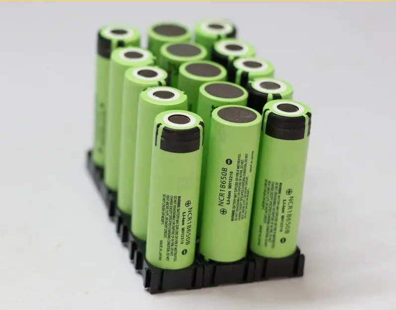
Figure (10): Battery placed in holder.
Step 3:
Next, we will be connecting the cells with nickel strips using the spot welding process. The series connection will be made by connecting the positive terminal of the cells to the negative terminal. The parallel connection will be made by connecting the same terminal. Figure (11) shows the nickel strips used for connecting batteries and figure (12.1), figure (12.2) and figure (12.3) spot welding process. Spot welding is done for the nickel strips connecting battery.

Figure (11): Nickel Strip
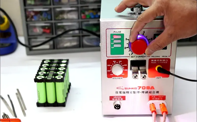
Figure (12.1): Spot Welding Process
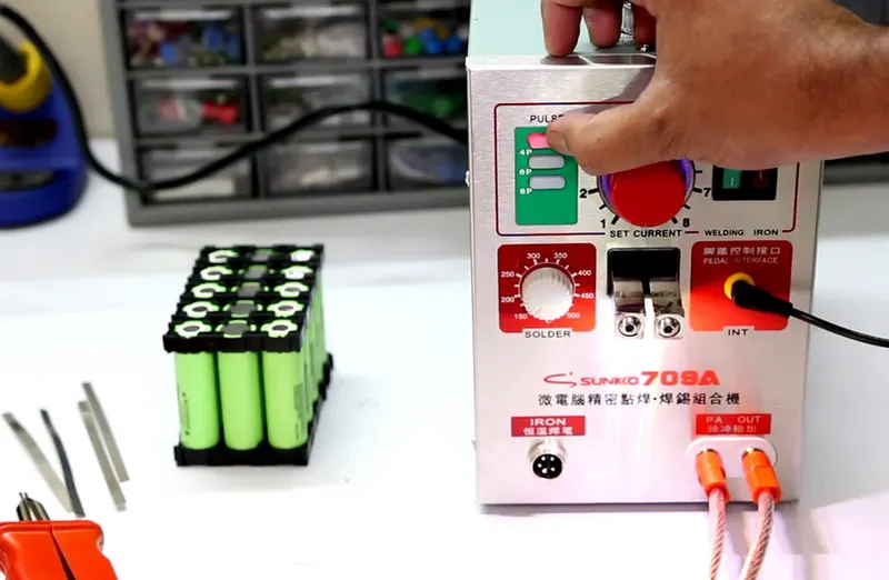
Figure (12.2): Spot Welding Process
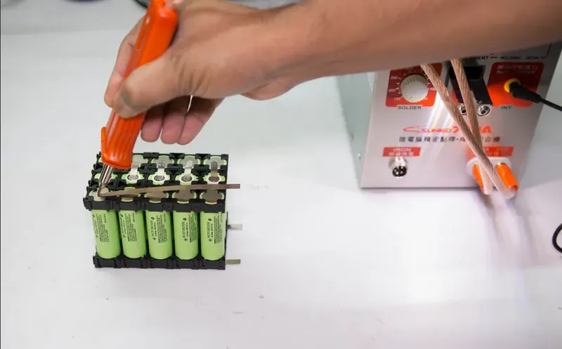
Figure (12.3): Spot Welding Process
Step 4:
Connecting the heat sink to the battery pack. Then we will be soldering the battery wire. Now the internal structure of the battery pack is assembled and all the terminals are connected as per the connections. Figure (13.1) and figure (13.2) shows assembling heat sink and wires soldering respectively.
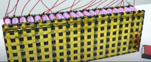
Figure (13.1): Heat sink assembled to the battery pack.

Figure (13.2): Wire soldering to the battery pack.
Step 5:
Connect the balancing wire pin to the battery management system. After the battery management system, the next and final step is to place the enclosure for the battery pack. Figure (14) shows BMS assembled with battery pack.
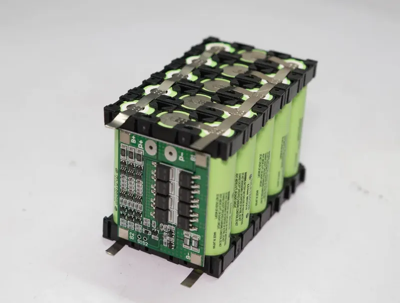
Figure (14): BMS assembled with battery pack
Conclusion:
The design calculation for the battery pack was carried out and calculated. The steps involved in the making of the battery pack have been listed out.