Project 1 Mechanical design of battery pack
AIM:
To develop a battery pack of 18KW using ANR26650M1-B cells along with their mechanical design.
THEORY:
One of the most important components of a battery-electric vehicle is the high voltage battery (BEV). The battery's specifications significantly affect the vehicle's other parts and characteristics, like maximum traction motor torque, maximum regeneration brake torque, vehicle range, vehicle total weight, vehicle price. The specifications of the high voltage battery determine pretty much all of the key features of a pure electric vehicle (EV).
Battery Pack:
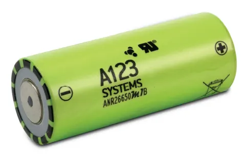
- A battery consists of one or more electrochemical cells (battery cells) which are converting chemical energy into electrical energy (during discharging) and electrical energy into chemical energy (during charging).
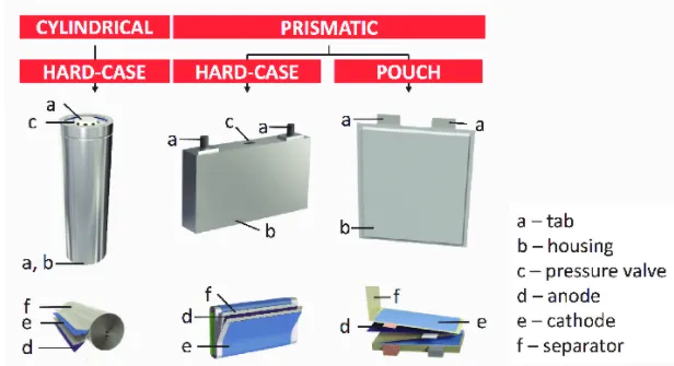
- The type of elements contained within a battery and the chemical reactions during discharging-charging events define the chemistry of a battery. A battery cell consists of five major components: electrodes – anode and cathode, separators, terminals, electrolyte and a case or enclosure
- Individual battery cells are grouped together into a single mechanical and electrical unit called a battery module.
- The modules are electrically connected to form a battery pack.
- There are several types of batteries (chemistry) used in hybrid and electric vehicle propulsion systems but we are going to consider only Lithium-ion cells. The main reason is that Li-ion batteries have higher specific energy [Wh/kg] and specific power [W/kg] compared with other types.
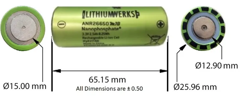
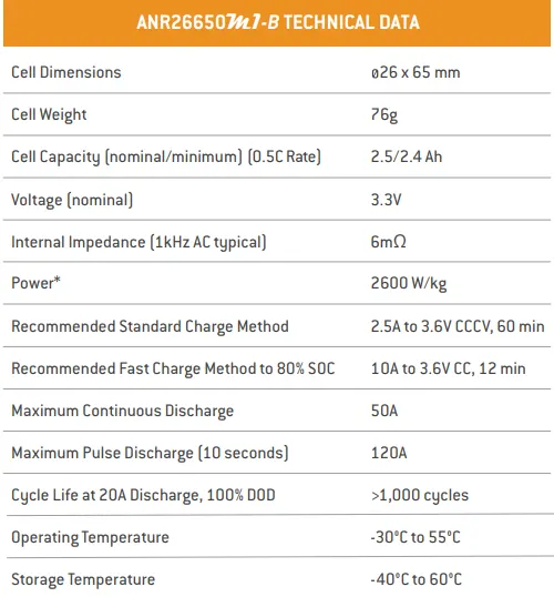
Cell parameters:
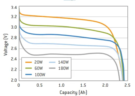
Constant Power Discharge Characteristics at 23°C
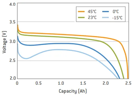
2.5C Constant Current Discharge at Various Temperatures
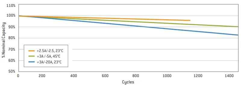
Cycle Life Performance, 100% DOD, Various Temperatures and Discharge Rates
A123’s high-performance Nano phosphate lithium iron phosphate (LiFePO4) battery technology delivers high power and energy density combined with excellent safety performance and extensive life cycling in a lighter weight, more compact package. Our cells have a low-capacity loss and impedance growth over time as well as high usable energy over a wide state of charge (SOC) range, allowing our systems to meet end-of-life power and energy requirements with minimal pack oversizing.
Calculations:
to calculate how much volume the cell will require to perform at 18 kw.
>> Volume of the cell
= π*r^2*h
= 3.14*0.013^2*0.065
= 0.0000344929 m^3
>> Energy of the cell
= Nominal cell voltage(V) * Capacity of the cell (Ah)
=3.3*2.5
= 8.25 Wh
>> Energy density of the cell
= Energy of the cell / Volume of the cell
= 8.25/0.0000344929
= 239,179.65 Wh/m^3
A battery pack module with the necessary capacity must be built using series and parallel cells in order to produce an output power of 18 kw.
Consider 58 cells in series a and 38 cells in parallel connected.
>> Total number of cells
= 58*38
= 2204 cells
>> Total voltage of the battery pack
= 58*3.3
= 191.4 volts
>> Total current capacity of the battery pack
= 38*2.5
= 95 Ah
>> Total energy of the battery pack
= Total voltage of the battery pack * Total current capacity of the battery pack
= 191.4 * 95
= 18183 Wh
= 18.18 KWh
Therefore, For the losses and connectivity restrictions, we should aim for more KWH than is actually needed.
We can now calculate the energy density, volume, and weight of the entire battery pack since we know the total number of cells that are required in it.
>> Total volume of the battery pack
= Total Number of the cells * Volume of the cell
= 2024 * 0.0000344929
= 0.0698136296 m^3
>> Total Weight of the battery pack
= Total number of the cells * Weight of the cell
= 2204 * 0.076
= 167.504 kg
Now we have all the parameters to construct a battery pack.
>> Battery pack construction
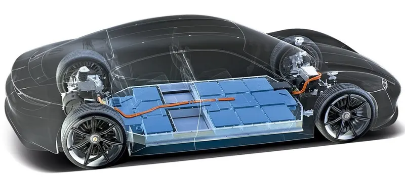
The batteries are connected 58S38P arrangement
There are few steps for the construction of the battery pack.
Step 1. Design of cell holder

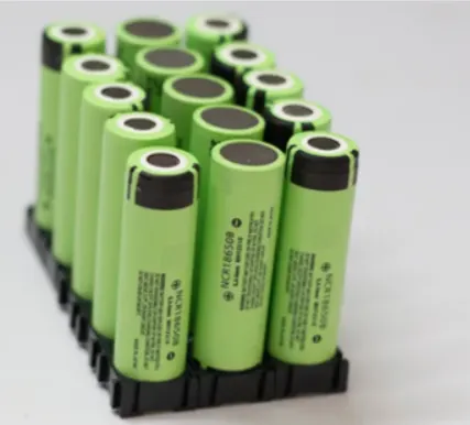
The primary purpose of a battery holder is to maintain cells fixed in place safely and securely. It is also used to maintain cells in a good arrangement to reduce mechanical vibration and improve the thermal runway between the gaps between the cells. Polypropylene or nylon bodies rated for 80-100 °C make up the majority of the cell holder's body.
Step 2. Connecting the cells
Now, using the spot-welding technique, we will join the cells together with nickel strips. The positive terminal of the cells will be connected to the negative terminal to create the series connection. The same terminal will be connected to create the parallel connection.
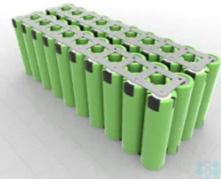
- Nickel strip is generally used in battery pack construction.
- Its due to its efficiency of usage in spot welding and soldering as well its high corrosion resistance over time.
- It has good properties and excellent resistance to many corrosive environments.
- The pure nickel will never get rust after it applied to battery packs.
- It won’t affect the current transfer between batteries. Pure nickel strips are the material you want, but many vendors swap out it for nickel-plated steel strips, which are poorer and have greater resistance – not suitable for most battery projects. 100% pure nickel strip.
- verify all of our strips to assure that you are getting the high-quality pure nickel. It also solders incredibly quickly, so you can weld them onto your existing busbar connections to raise the supply of current you can pull through the busbars. The benefits are nearly limitless!
Step 3. Battery enclosure and thermal management of battery and BMS
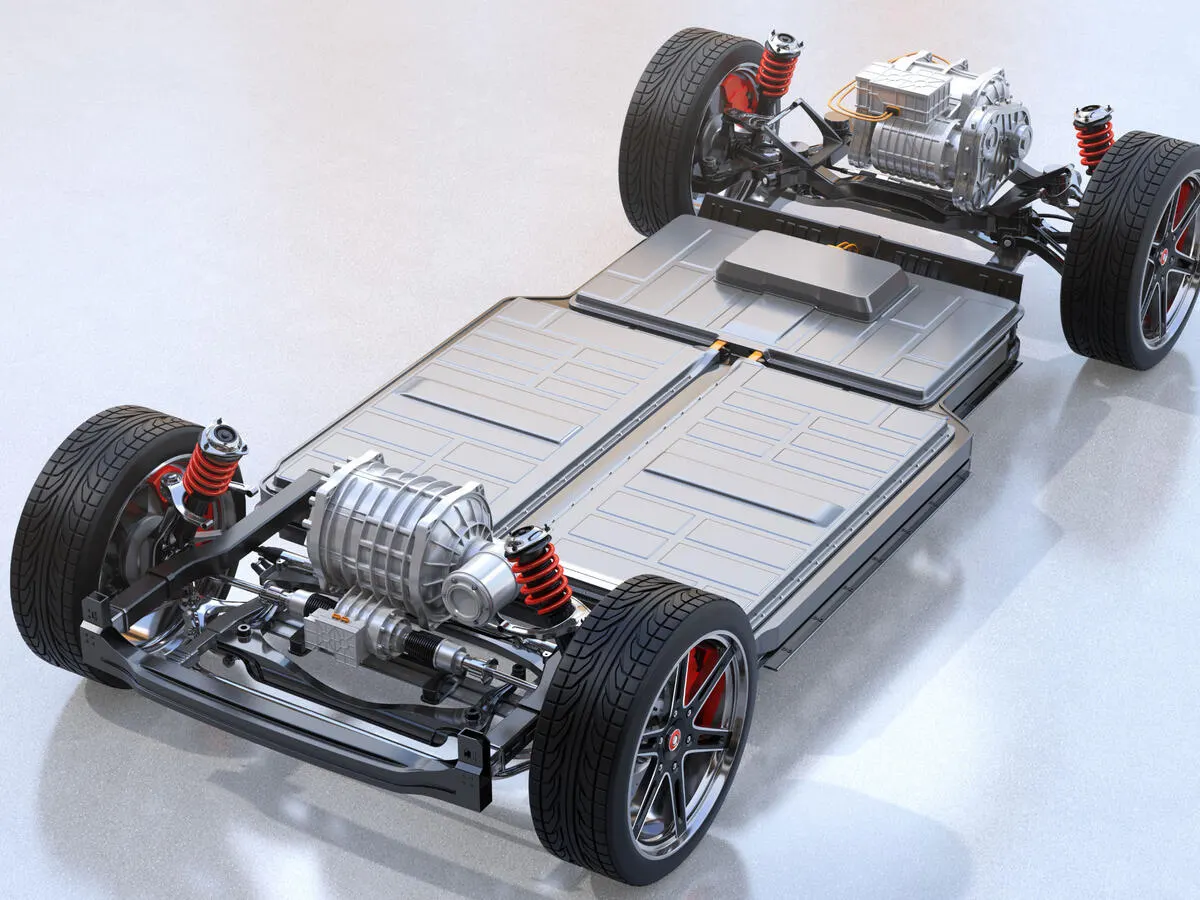
The battery's final method of protection is the enclosure. Therefore, the battery enclosure needs to be both exceedingly sturdy and lightweight. Because batteries have a tendency to catch fire in the case of a collision if they leak during a collision, the battery module is enclosed in a highly sturdy enclosure for safety. To achieve the best possible range, the weight should be lower. When necessary to obtain the most performance out of the batteries, a temperature management system is installed in this metal container to cool and heat the batteries. To construct a full battery pack, numerous versions are connected in parallel and series.
Battery management system (BMS)
Functions:
- Monitors all of the parallel groups in the battery pack and disconnect it from the input power source when fully charged.
- Balance all the cells voltage equally.
- Avoid overcharging.
- Thermal management.
- Optimal energy utilization.
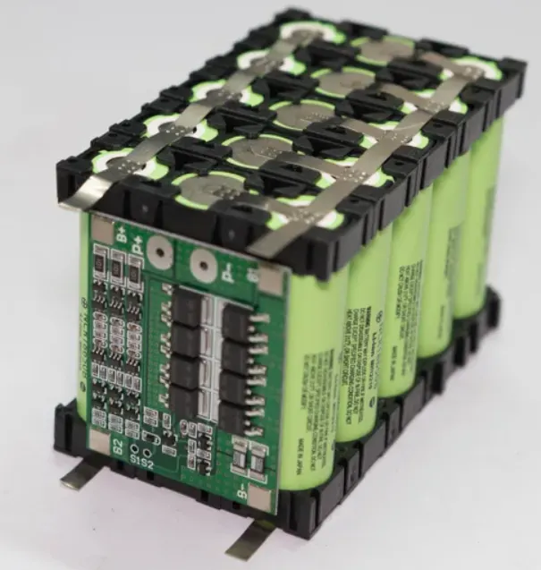
Final battery pack is created.
Conclusion :
Using the given cell parameters the design calculation is carried out and the mechanical design of the battery pack is completed.