Project 1 Mechanical design of battery pack
PROJECT 1- Mechanical Design of Battery Pack
Battery pack capacity: 18 kWh
Cell: ANR26650M1-B
Prepare a detailed battery pack drawing along with its enclosure. State your assumptions.
ANR26650M1-B Cell
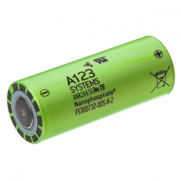
A123’s high-performance Nanophosphate lithium iron phosphate (LiFePO4) battery technology delivers high power and energy density combined with excellent safety performance and extensive life cycling in a lighter weight, more compact package.
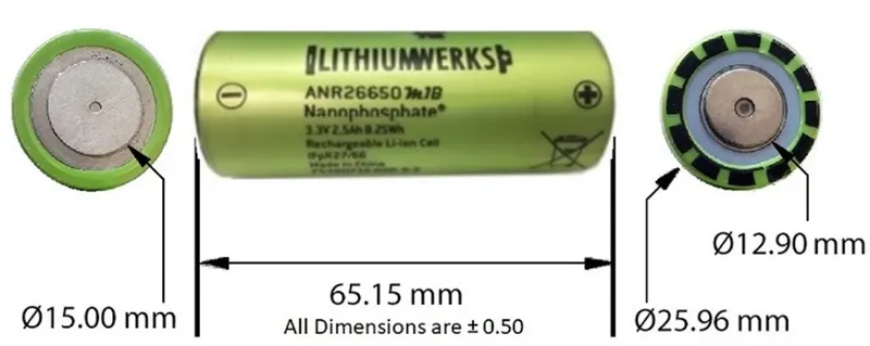
Cell Dimensions
Applications
Commercial Solutions:
Advanced lead acid replacement batteries for:
- Datacenter UPS
- Telecom backup
- IT backup
- Autonomously guided vehicles (AGVs)
- Industrial robotics and material handling equipment
Government Solutions:
- Military vehicles
- Military power grids
- Soldier power
- Directed energy
Grid Solutions:
- Frequency regulation
- Renewables integration
- Reserve capacity
- Transmission and distribution
Transportation Solutions:
Hybrid, plug-in hybrid and electric vehicle battery systems for:
- Commercial vehicles
- Off-highway vehicles
- Passenger vehicles
Technical Data
Cell Dimensions- 26 dia x 65 mm
Cell Weight- 76g
Cell Capacity (nominal/minimum) (0.5C Rate)- 2.5/2.4 Ah
Voltage (nominal)- 3.3V
Internal Impedance (1kHz AC typical)- 6mΩ
Power- 2600 W/kg
Recommended Standard Charge Method- 2.5A to 3.6V CCCV, 60 min
Recommended Fast Charge Method to 80% SOC- 10A to 3.6V CC, 12 min
Maximum Continuous Discharge- 50A
Maximum Pulse Discharge (10 seconds)- 120A
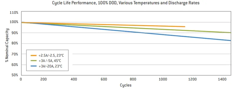
Cycle Life at 20A Discharge, 100% DOD- >1,000 cycles
Operating Temperature- -30°C to 55°C
Storage Temperature- -40°C to 60°C
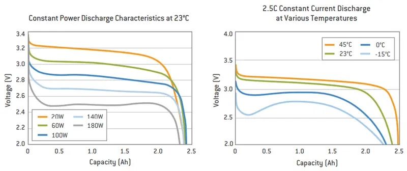
Cell Characteristics
Battery Pack Design
Battery pack capacity= 18 kWh
Voltage i/p= 400v
So we require 400v and 18Kwh to run the EV.
Given, The voltage of single cell= 3.3v and cell capacity= 2.5Ah, so to make 400v we have to connect the cells in series (to increase the voltage). Therefore 400/3.3= 121.21= 122 cells module in series. So we have achieved the voltage requirement.
Now for the energy requirement,
Energy of one cell= 2.5x3.3= 8.25Wh= 0.00825 kWh
Energy of 122 cell module in series= 122x0.00825= 1.0065kWh, which is not enough. So to construct a battery pack with 18kWh energy and not exceeding 400v, the modules are connected in parallel. In this parallel connection, the currents is getting added and the voltage remains same as 400V. As current increases the power of battery pack increase.
So, 18/1.0065= 17.88= 18, so 18 similar modules in parallel is required to get a battery pack of 18kWh energy.
So total no. of cells in the battery pack= 122x18= 2196 cells.
Battery configuration is 122S18P. 122S gives 400V and this module in 18 parallels gives (2.5x18) 45Ah. So 122S18P battery pack together gives (45x400) 18kWh energy. And this pack is fitted to the Ev chassis.
Calculation of Size of Ev Battery Tray
Length of 122S module (L)= No. of cells in series x (diameter of cell+margin at both side of cell) + clearance at each side
L= 122x(26+4) + 2x(diameter of cell+margin)
L= 122x(26+4) + 2x(26+4)= 3660 + 60
L = 3720mm
Width of module (W)= No. of cells in parallel x (diameter of cell+margin at both side of cell) + clearance at each side
W= 18x(26+4) + 2x(diameter of cell+margin)
W= 18x(26+4) + 2x(26+4)= 540 + 60
W= 600mm
Height of the module (H)= Height of cell + margin for wiring,etc..
H= 65 + 35= 100mm
Total Volume of the battery tray (V)= LxWxH
V= 3720x600x100= 2232x10^(5) mm^3= 0.2232 m^3
Weight of the 122S18P battery pack= Total no. of cells in the pack x weight of single cell
Weight= 2196 x 76= 166896g= 166.896 Kg
Considering the weight of other accessories, Total weight= 170Kg
Joining of Cells for the Final Battery Pack
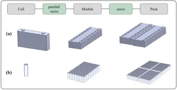
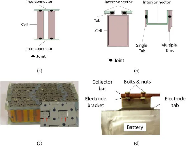
There exist different battery types and thus different joining tasks can be defined. Generally, batteries being connected in parallel or in series are interconnected by means of joining them to an interconnector, i.e. an electric conductor, it is also known as collector bar or busbar. Pouch and also prismatic cells may be connected as shown in below figure. The major difference is that in the case of cylindrical cells the interconnector will be directly joined onto the cell housing whereas pouch and prismatic cells have externally located connector tabs which are joined to the interconnector.
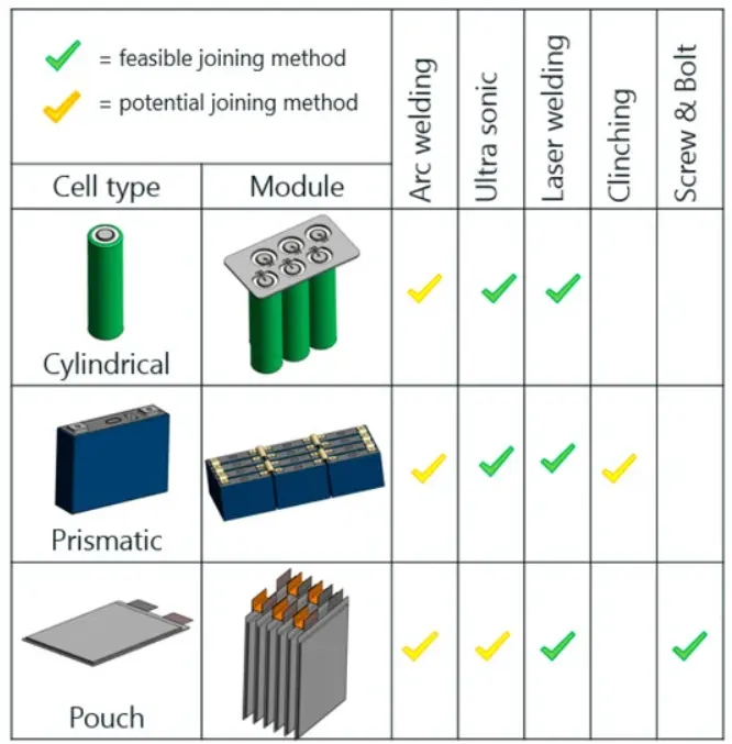
The most commonly deployed joining technologies are ultrasonic welding, wire bonding, force fitting/mechanical assembly, soldering and brazing, laser and resistance spot welding.
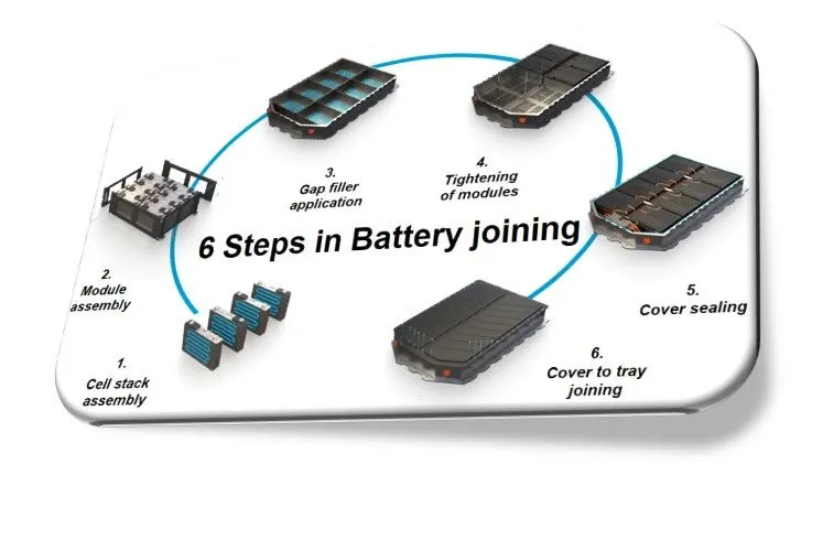
Final EV Battery Pack
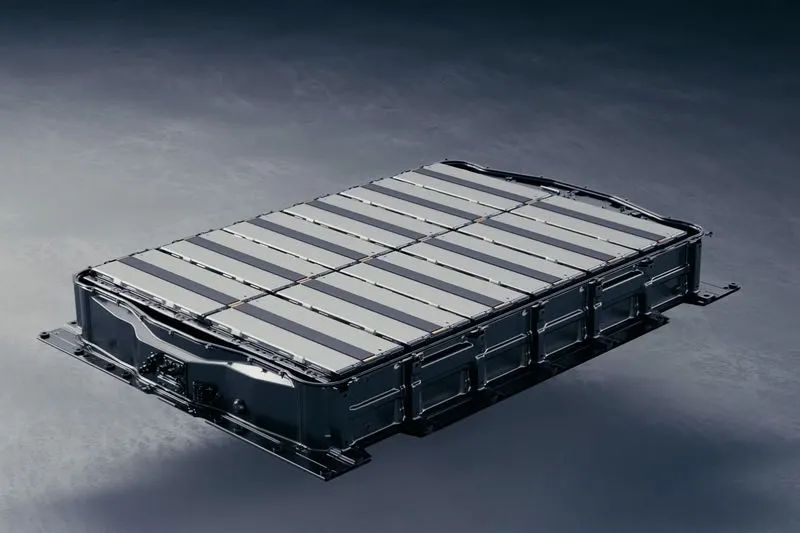
Finally the overall battery pack after the arrangement of all connections with enclosure will looks like as shown in the above figure. Vents holes are also present for cooling or heating the battery pack according to the environmental conditions.