Project 1 Mechanical design of battery pack
AIM:
Design a mechanical battery pack.
OBJECTIVE:
Battery pack capacity: 18 kWh
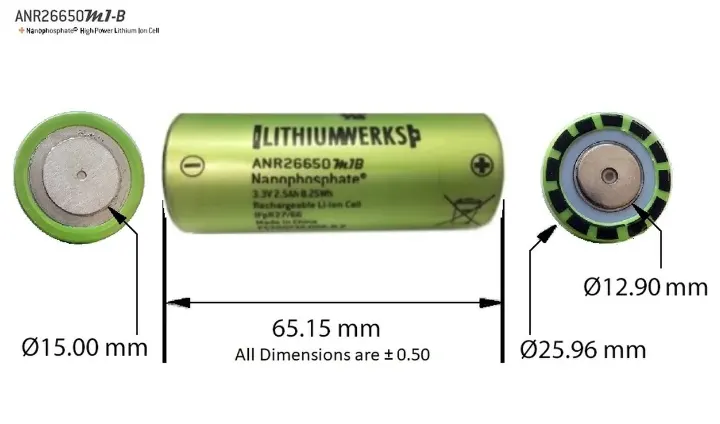
Cell: ANR26650M1-B
Prepare a detailed battery pack drawing along with its enclosure. State your assumptions.
INTRODUCTION:
As electric vehicles are increasing in the market is gradually increasing, there is considerable growth in the production of lithium-ion batteries. As it is the electrical source for the EV.
A lithium-ion battery or Li-ion battery is a type of rechargeable battery in which lithium ions move from the negative electrodes through an electrolyte to the positive electrode during discharge, and back when charging. Li-ion batteries use an intercalated lithium compound as the material at the positive electrode and typically graphite at the negative electrode.
Lithium-ion batteries are made use of various different electrodes. The most common material use is lithium cobalt oxide and graphite which are most commonly found in portable electronic devices such as cellphones and laptops. Lithium manganese oxide and lithium iron phosphate are also used as cathode materials.
Applications:
Commercial Solutions:
Advanced lead acid replacement batteries for:
- Datacenter UPS
- Telecom backup
- IT backup
- Autonomously guided vehicle (AGV's)
- Industrial robotics and material handling equipment
- Medical devices
Government Solutions:
- Military vehicles
- Military power grids
- Soldier power
- Directed energy
Grid Solutions:
- Frequency regulation
- Renewables integration
- Reserve capacity
- Transmission and Distribution
Transportaion Solutions:
- Commercial vehicles
- Off-highway vehicles
- Passenger vehicles
CELL SPECIFICATIONS: (ANR26650M1-B)
| Nominal Voltage | 3.3V |
| Nominal Capacity | 2.5Ah |
| Maximum discharge current - continuous (A) |
70A, with the caveat, that the cells do NOT exceed their maximum operating temperature (+60°C) |
| Pulse discharge at 10 sec | 120A |
| Peak power @ 10 s (watts) | 210W |
| Recommended standard charge | 1.5C to 3.6 V |
| Recommended fast charge | 4C to 3.5V |
| Recommended float charge voltage | 3.5V |
| Recommended end of discharge cutoff |
2.0V |
| Operating Temp Range | -30°C to +60°C |
| Storage temperature range | -40°C to +60°C |
| Weight | 75 grams |
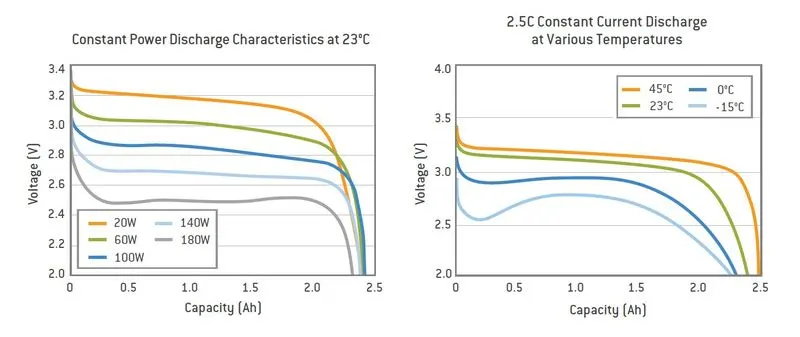
Here you can see the voltage capacity of the battery for different power ratings.
DESIGN CALCULATION
All the parameters of this calculation are taken from the datasheet
Common terms used in Battery:
Voltage : Total voltage, voltages of individual cells, minimum and maximum cell voltage, or voltage of periodic taps. To maximize the battery's capacity and to prevent localized undercharging or overcharging, the BMS may actively ensure that all the cells that compose the battery are kept at the same voltage or the State of charge, through balancing. The maximum voltage at the time of charging and nominal voltage during the operation of the battery is with to mention her.
Temperature : Average temperature, coolant intake temperature, coolant output temperature or temperature of individual cells.
State of Charge(SOC) : Depth of charge(DOD) to indicate the charge level of the battery.
State of Health(SOH) : A variously defined measurement of the remaining capacity of the battery as % of the original capacity.
State of Power(SOP) : The amount of power available for a defined time interval given the current power usage, temperature and other conditions.
Charging-Discharging Current : Current In or Out of the battery respectively.
About cell:
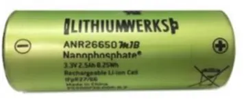
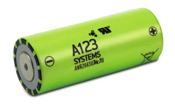
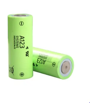
The LithiumWerks ANR26650M1-B is the next generation of A123 Systems' pioneering 26650 cylindrical cell, now with greater power and energy density and lower impedance. This versatile lithium ion cell is suitable for a wide variety of applications and system designs.
About module:
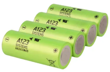
A battery management system (BMS) is any electronic system that manages a rechargeable battery (cell or battery pack), such as by protecting the battery from operating outside its safe operating area, monitoring its state, calculating secondary data, reporting that data, controlling its environment.
About Battery pack:
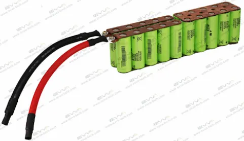
A battery pack is a set of any number of (preferably) identical batteries or individual battery cells. They may be configured in a series, parallel or a mixture of both to deliver the desired voltage, capacity, or power density.
CALCULATIONS:
Now let's calculate that, how many of cells were needed as series and parallel arrangement to satisfied the 18 kWh battery capacity,
Solutions
1. Calculate Cell Energy
- For single cell,
Nominal Voltage,V = 3.3 V
Nominal Current,I = 2.5 A
Nominal Capacity = 2.5 Ah
Nominal Cell Energy, Ec = Voltage * capacity = 3.3 * 2.5 = 8.25 Wh
2. Series and Parallel Battery Pack Assembly
- By assumption,
No.of cells in series = 44
No.of cells in parallel = 50
Total no.of batteries = Series * Parallel = 44*50 = 2200 cells
So the configuration of the pack is 44S 50P
4. Energy Calculation of the Battery Pack
For overall energy calculation of battery pack, Ebp = Total no.of batteries * cell energy = 2200*8.25 = 18150 Wh = 18.15 kWh
- The above result were almost attained the specified energy capacity (18kWh) of the battery pack
5. Calculate the Voltage and Current of the Battery Pack
Series configuration:
Voltage of battery pack,
Thus the voltage of the battery pack is 145V
Parallel configuration:
Current of battery pack,
Thus the current of the battery pack is 125A
Capacity of the battery pack (energy stored) = 125Ah = 18.15kWh
6. Calculate the Battery Pack Dimensions (Mechanical Design)
- For single cell,
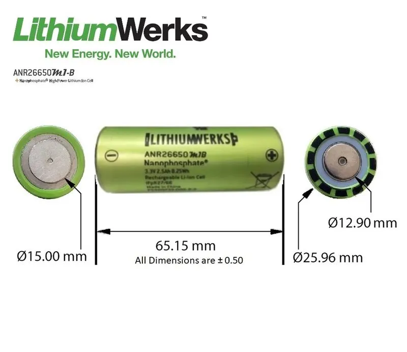
Diameter, dc = 25.96 mm = 0.02596 m
Radius, rc = 12.98 mm = 0.01298 m
Height, hc = 65.15 mm = 0.06515 m
Volume of the single cell (cylindrical), Vc =
For the entire battery pack (2200 cells),
Volume of the battery pack = 2200 *
Note: The dimensions of the battery pack has calculated on for the cells, the calculation has not included with the additional components (BMS and communication)
7. Calculate the Battery Pack Mass
For single cell, mc = 76 g
Mass of multi-cell in battery pack = 2200 * 76 = 167200 grams = 167.2 kg
Note: The mass of the battery pack has calculated were excluded the vehicle's additional components (wires, electronic components, soldering, case, etc.)
8. Calculate the Volumetric Energy Density of the Battery Pack
For battery pack,
9. Calculate the Gravimetric Energy Density of the Battery Pack
For battery pack,
10. Energy Consumption of Battery Pack for Certain Distance
Let assume the vehicle has completely charged (100% SoC) and now it's travelled 75 kms,
Now estimate the total battery pack energy usage,
= Overall energy of battery pack (Wh) / vehicle travelled (kms)
=
So the vehicle has consumed the energy of 242 Wh for 75 kms travel.
The above calculation is to find the total number of cells for a full battery pack for an Electric vehicle, also the battery pack weight, current, capacity, and voltage.
A battery pack is a system of multiple components and functions and its design involves the application of knowledge and practice in the electrochemical, electrical, mechanical, thermodynamic, and control fields. The following sections summarize the various stages of a battery pack design, covering specific aspects of the A123 cells which may be unique from other cells.
Mechanical Connection :
Design mechanical interconnects to prevent accidental short circuits. Size these mechanical interconnects to carry the expected maximum rated current for both the maximum time and ambient temperature in which the pack is expected to operate.
Cell Interconnects :
Size cell interconnects for the expected maximum current carrying capability. Improperly sized tabs could heat up excessively, resulting in even higher resistivity. For reliable welded connections at the terminals, A123 Systems recommends either pure nickel tabs or nickel-clad copper tabs. In addition, other alloys afford both weldability, strength, and low resistance, which are all desirable features of a good interconnection. Cell interconnects (tabs) should be neither soldered on the end caps nor attached using extreme heat. A123 Systems recommends tabs be resistant or laser-welded to both ends of the cells. Resistance welding provides a constant current for a specified period of time through a salient feature in the weld tab. These parameters can be specified and regulated for a consistent high-quality weld every time.
The Gap Between Each Cell :
The cell vents, located on the end cap(s) of the cells (on the POSITIVE side of the cell), should not be blocked by any mechanical means. Blocking the cell vent and then sufficiently abusing the cell to build up pressure in the cell prevents the cell from properly venting. An ESS designed to install cells end-to-end needs at least 1 mm of space between the cells to allow the vent to open under fault conditions.
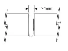 Mechanical design of battery pack : Skill-Lync" />
Cell Design and Assembly of Battery Pack -
Single Cell Dimensions :
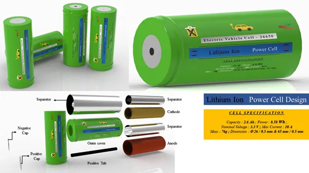
A Cell is basically consisting of Anode, Cathode, Separator, Positive Cap, Negative Cap, and Gasket -
The arrangement design of single-cell is shown below -
Cylindrical cells:
Cylindrical cells are the most common cell type in use today. This design allows for better automation processes and techniques that increase consistency and lower cost.
Compared to prismatic cells, cylindrical cells can be produced much faster so more KWh per cell can be produced every day equaling lower $ per kWh. The electrodes in a cylindrical cell are wound tightly and encased in a metal casing, This minimizes electrode material from breaking up from the mechanical vibrations, thermal cycling from charging and discharging, and mechanical expansion of the current conductors inside from thermal cycling. Many cells are combined in series and in parallel to increase the voltage and capacity of the battery pack. If one cell goes bad, the impact on the entire pack is low. With prismatic cells, if one cell goes bad it can compromise the whole battery pack. Cylindrical cells radiate heat and control temperature more easily than prismatic cells.
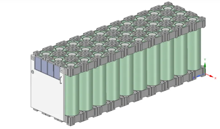
Here we use the lego connector Because In this easy to connected cells, when one cell fails, easy to deconstruct.
Series Strings :
Cells combined in series strings can achieve higher operating voltages by connecting the positive terminal of one cell to the negative terminal of the next cell. Connect strings of series cells using their current collection tabs like that illustrated in Figure -
Parallel Strings :
Cells combined in parallel strings can achieve higher operating capacities by connecting like-polarity terminals of adjacent cells. Connect strings of parallel cells using their current collection tabs like that illustrated in Figure -
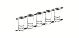
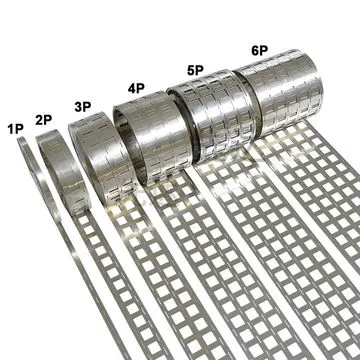
Nickel Strips :
Conductive metal strips are spot welded between all the cells of an electric bicycle battery pack. Nickel is the material of choice due to its low relative resistance and ease of spot welding. Steel is cheaper than nickel, which is why many vendors sell nickel-coated steel strips. It brings the cost down, but at the expense of pack health. Because steel has higher resistance, the same size strips will heat up more, wasting energy from your pack. This not only cuts down on your range but also damages your battery by cooking it slowly over time with extra heat.
 Mechanical design of battery pack : Skill-Lync" />
- The first step in the design of the pack is to determine the configuration of cells, i.e. how many cells overall, how many are in series, and how many are in parallel. This is the foundation of the design process since all other design decisions follow the cell configuration.
- The second step is to design a mechanical structure around the cells to support and protect them. This step requires knowledge of electrical, mechanical and thermodynamic requirements and properties of the cells, application, and the materials used in the pack.
- The third step is to design the protection of the cells, particularly electrical protection. The pack must be protected from inadvertent short circuits internal and external to the pack as well as excessive charging and discharging imposed on its terminals.
- The fourth step is to design a control system that monitors and manages the cells, keeping them from being damaged and maintaining the pack at peak performance.
- Finally, a pack performs best when it is used properly. The final section of this chapter describes how to charge and discharge the battery pack to make it perform its best.
General Steps to Design a practical Battery Pack :
Step 1 -
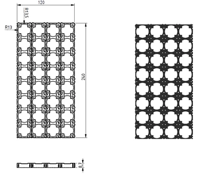
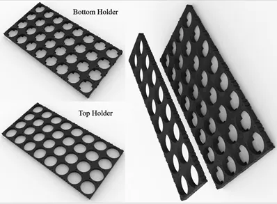
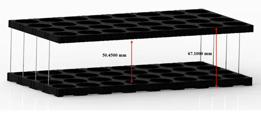
Design of cell holder (Bottom and Top) :
The main function of a battery holder is to keep cells fixed in place safely and securely also it is used to keep cells in a proper arrangement so that there will be a decrease in mechanical vibration, and have a better thermal runway in between the gaps of the cell. Most of the cell holder is made up of polypropylene or nylon bodies rated for 80–100 °C.
Step 2 -
Inserting cells inside the holder (Bottom and Top) :
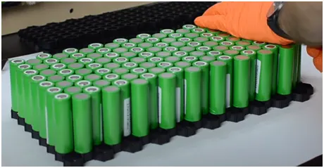
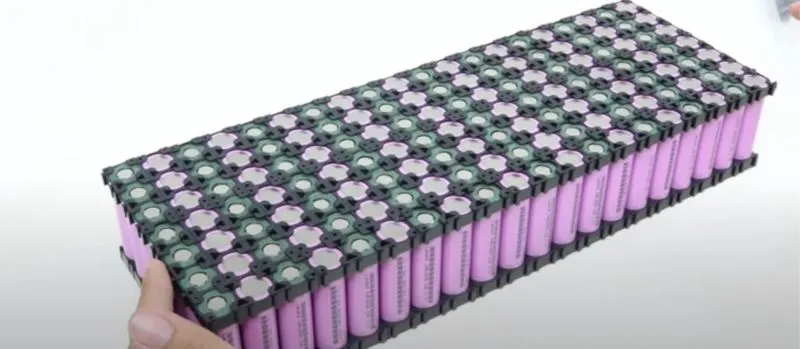
Insert the cells inside these connectors with positive and negative poles kept alternatively in adjacent rows.
Step 3 -
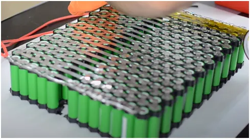
Spot welding :
Spot weld with nickel strips to make a series connection between the cells as shown -
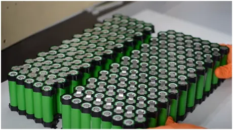
After making series connections, connect the strings in parallel. And complete the connection below -
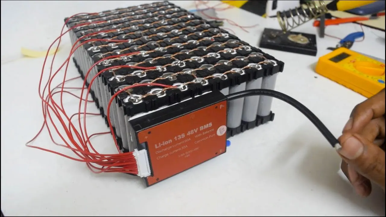
Step 4 -
Install BMS for the battery pack as shown -
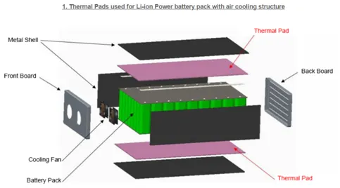
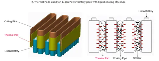
Step 5 -
Install cooling structures for air cooling/ liquid cooling as shown -
Step 6 -
Install the battery pack inside the enclosure as shown -
Enclosure for battery packs :
There are different types of enclosures available for the battery pack. A few are explained below. The main features required for EV battery enclosures are :
- Lightweight
- Shock and Vibration-proof
- Fire protection
- Prevent Electromagnetic radiation
- Low cost
- Aluminium sheet battery enclosure
Aluminium sheet battery enclosure -
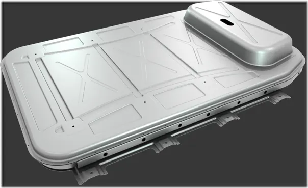
Aluminium's inherent properties — corrosion resistance and recyclability — make the metal attractive in electric-vehicle manufacturing. The enclosure regulates thermal conductivity by helping to cool and heat the battery cells.
Using aluminium to enclose a lithium-ion battery pack in an EV can reduce weight by about 50 per cent.
Weight savings translates into a longer driving range, a major challenge for the competitiveness of electric vehicles.
The lightweight aluminium translates into a lower cost per weight at mass-production volumes.
Conclusion:
Lithium Ion and Lithium Ion Polymer batteries are a great power source for some applications but they require preventive protection during discharging and charging.