Project 1 Mechanical design of battery pack
QUESTION:
Battery pack capacity: 18 kWh
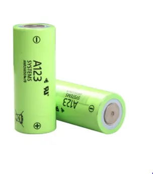
Cell: ANR26650M1-B
ANSWER:
Mechanical design of a battery pack :-
One of the fundamental components of an electric powertrain is the battery pack. The battery pack is the energy source for the vehicle, and for high-performance vehicles, it must supply energy to the vehicle at very high power. The automotive environment is especially challenging for batteries, as the batteries are subject to a wide range of operating conditions. Thermal considerations are critical to the safety and performance of battery packs, a challenge that is intensified in cars because of the increased heat generation in batteries at high charge and discharge rates, which are necessary for high power output. Mechanical robustness is also a critical challenge, the battery pack must not only be able to withstand vibration and loads from normal driving conditions and accelerations and decelerations, but also maintain structural integrity in crash scenarios. This is especially important for safety because impac lithium ion batteries can be extremely dangerous and cause catastrophic failure of the entire battery pack.
A battery pack is a set of any number of (preferably) identical batteries or individual battery cells. They may be configured in a series, parallel or a mixture of both to deliver the desired voltage, capacity, or power density. The term battery pack is often used in reference to cordless tools, radio-controlled hobby toys, and battery electric vehicles.
Cells :-
A cell refers to a single anode and cathode separated by electrolyte used to produce a voltage and current. A battery can be made up of one or more cells. A single AA battery, for example, is one cell.
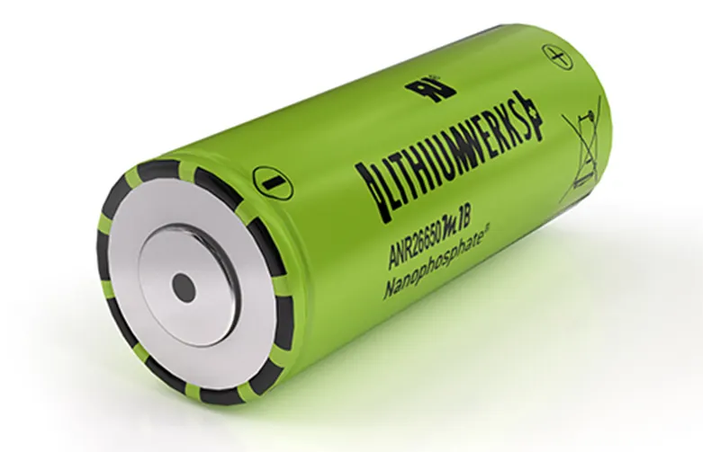
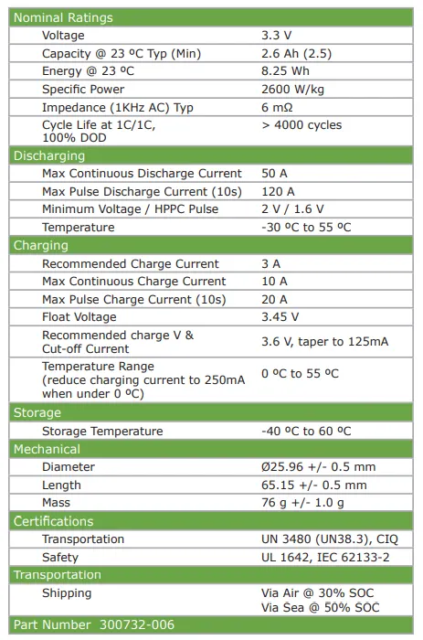
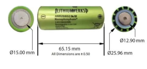
Cell: ANR26650M1-B Datasheet .
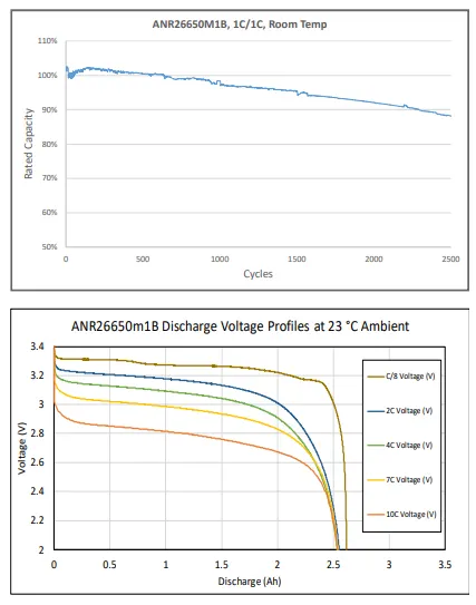
Li-ion cell(ANR26650M1-B):
This Li-ion cell is manufactured by Lithiumwerks.They deliver very high power due to their use of patented Nanophosphate battery technology.
Based on the Lithium iron phosphate chemistry (LiFePO4),the cells are inherently safe over a wide range of temperature and conditions, For outstanding cycle life,stable float reliability this cells are suitable for a wide varity of power,pulse and stand by applications.
Nanophosphate battery technology offers thermal stable chemistry,fast charging.consistent output,low capacity loss over time. It provides extremely safe conditions for while meeting most demanding customers requirements.Multiple layers of protections are employed on chemistry.cell and system level to acheive an energy storage solution with superior safety.
Electrical Configuration :-
Single cell has voltage of 3.3V and 2.56Ah of ratings.
Capacity of single cell :-
3.3V*2.56Ah = 8.448 watt hour
Assuming Battery pack voltage of 330 V.
Series connection of cells:-
Each cell voltage is 3.3V and pack voltage should be 330 Volt, therfore 100 cells are needed to be connected in series.
Ns = 330/3.3 = 100 cells.
Parellel connection of cells :-
Required capacity is 18000wh
As voltage is assumed to be 330 V
Therfore current output at terminals of battery pack is
18000/330 = 54.54Ah.
Single parallel path produces 2.56Ah,
Therfore,
54.54/2.56 = 21.3 = 22(approximately) parallel connections are required.
Total Number of cells are:-
Number of cells in series mulipiled by number of cells in parallel 100*22 = 2200 cells are required.
Cell architecture 100 Series and 22 Parallel = 100S22P
Mechanical design of battery pack :-

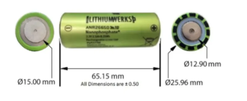
length of cell is 66mm
diameter of cell is 26mm
Module:-
To increase cell ratings , same types of cells are connected in series and parallel.
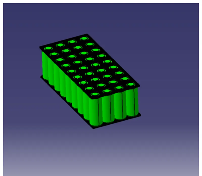
Extra 2mm length is taken for cell strips and distance between cells assume to be 4mm. Assuming 25 cells are connected in series in module.
Therefore,rating of cell is
Voltage = 25*3.3 = 82.5V
Ampere hour remains constant as cells are connected in series.
Therefore, One module consists of 25 cells.
Total modules = 2200/25 = 88
If we connect four modules in series, It deliver 330V and 2.35Ah and here it form one parallel path.
Each parallel path consist of four modules and these should be repeated for remaning 22 parallel paths.
If connect 88 modules then it will become battery pack.
This is one of the module configuration. Other module configurations are also possible.
Connections of cells :-
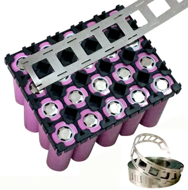
Cell are connected with the help of Nickel strips as shown in below figure.
Nickel strips are used because of their heat capablities.
Welding:-
To connect cells the nickel strips are used. Welding has to be done to connect cell to nickel strip.
Types of welding are
1. Spot Weld
2. Laser weld
3. wire bond
Calculating volume and weight of a module :-
considering Protection Venting, Nickle strip and Foil based component and battery the Length is 70mm.
Length of casing (L) = number of cells at series * [cell diameter (26) + margin at both side of cell (4)] + clearance at side (diameter of edged cell +margin)
L=[100*(30)]+60
L = 3060mm
Breadth of casing (B) = number of cells at parallel * [cell diameter (26) + margin at both side of cell (4)] + clearance at side (diameter of edged cell + margin)
B=[22*(30)]+60
B = 720mm
Height of casing (H) = 66 + 35 (Height of cell + margin for wiring Cell holders and metal strips)
H = 101mm
Weight of battery pack
Cell weight = 76g
Number of the cells = 2200
Battery pack weight (W) = cell weight * number of cells + weight of accessories
W=76 * 2200 + 4.5
W =167200 + 4.5
W =167.2 kg

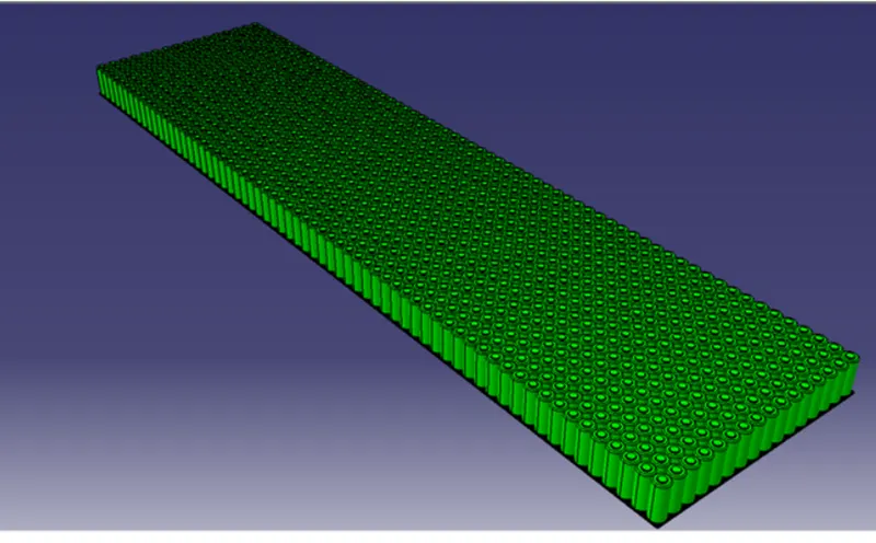
Above fig. shows the total battery pack.
Design Overview
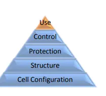
A battery pack is a system of multiple components and functions and its design involves the application of knowledge and practice in the electrochemical, electrical, mechanical, thermodynamic, and control fields. The following sections summarize the various stages of a battery pack design, covering specific aspects of the A123 cells which may be unique from other cells.
- The first step in the design of the pack is to determine the configuration of cells, i.e. how many cells overall, how many are in series, and how many are in parallel. This is the foundation of the design process since all other design decisions follow the cell configuration.
- The second step is to design a mechanical structure around the cells to support and protect them. This step requires knowledge of electrical, mechanical and thermodynamic requirements and properties of the cells, application, and the materials used in the pack.
- The third step is to design the protection of the cells, particularly electrical protection. The pack must be protected from inadvertent short circuits internal and external to the pack as well as excessive charging and discharging imposed on its terminals.
- The fourth step is to design a control system that monitors and manages the cells, keeping them from being damaged and maintaining the pack at peak performance.
- Finally, a pack performs best when it is used properly. The final section of this chapter describes how to charge and discharge the battery pack to make it perform its best.
Mechanical Connection :
Design mechanical interconnects to prevent accidental short circuits. Size these mechanical interconnects to carry the expected maximum rated current for both the maximum time and ambient temperature in which the pack is expected to operate.
Cell Interconnects :
Size cell interconnects for the expected maximum current carrying capability. Improperly sized tabs could heat up excessively, resulting in even higher resistivity. A123 Systems recommends either pure nickel tabs or nickel-clad copper tabs for reliable welded connections at the terminals. In addition, other alloys afford both weldability, strength and low resistance, which are all desirable features of a good interconnection. Cell interconnects (tabs) should be neither soldered on the end caps nor attached using extreme heat. A123 Systems recommends tabs be resistant or laser-welded to both ends of the cells. Resistance welding provides a constant current for a specified period of time through a salient feature in the weld tab. These parameters can be specified and regulated for a consistent high-quality weld every time.
Battery Dimensions :
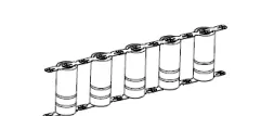
Series Strings:
Cells combined in series strings can achieve higher operating voltages by connecting the positive terminal of one cell to the negative terminal of the next cell. Connect strings of series cells using their current collection tabs like that illustrated in Figure.
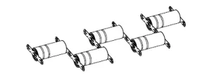
Parallel Strings :
Cells combined in parallel strings can achieve higher operating capacities by connecting like-polarity terminals of adjacent cells. Connect strings of parallel cells using their current collection tabs like that illustrated in Figure.
We Using Cylindrical cell :
Cylindrical cells are the most common cell type in use today. This design allows for better automation processes and techniques that increase consistency and lower cost.
Compared to prismatic cells, cylindrical cells can be produced much faster so more KWh per cell can be produced every day equaling a lower price per kWh. The electrodes in a cylindrical cell are wound tightly and encased in a metal casing, This minimizes electrode material from breaking up from the mechanical vibrations, thermal cycling from charging and discharging and mechanical expansion of the current conductors inside from thermal cycling. Many cells are combined in series and in parallel to increase the voltage and capacity of the battery pack. If one cell goes bad, the impact on the entire pack is low. With prismatic cells, if one cell goes bad it can compromise the whole battery pack. Cylindrical cells radiate heat and control temperature more easily than prismatic cells.
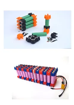
Here we using the lego connector Because In this easy to connected cells, when one cell fails, easy to deconstruct.
the same way the best electrical and mechanical connection.
Nickel Strips :
Conductive metal strips are spot welded between all the cells of an electric bicycle battery pack. Nickel is the material of choice due to its low relative resistance and ease of spot welding. Steel is cheaper than nickel, which is why many vendors sell nickel-coated steel strips. It brings the cost down, but at the expense of pack health. Because steel has higher resistance, the same size strips will heat up more, wasting energy from your pack. This not only cuts down on your range but also damages your battery by cooking it slowly over time with extra heat.
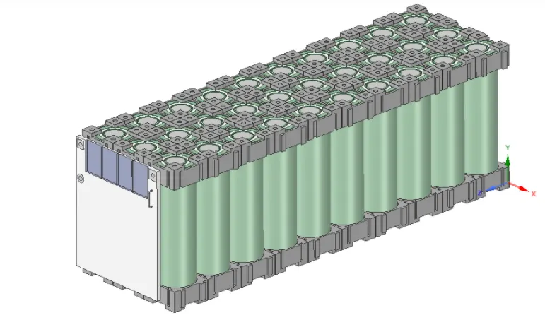

The Mechanical battery pack overall view from starting to end :
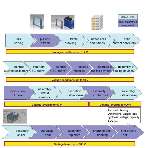
BATTERY PACK Exploded view:

CONSULATION:
Total Battery Consulting’s aim is to make available to industry professionals around the world information that can help them focus their financial and human resources on the most technologically viable and economically affordable options to meet the needs of the automotive energy-storage industry.