Project 1 Mechanical design of battery pack
Aim:- To prepare a mechanical model of an 18kwh battery pack
Cell parameters:-
ELECTRICAL DESIGN
Cell capacity - 2.5 Ah
Voltage - 3.3 V
Parallel configuration(Cells in a module)
160*2.5 = 400Ah
Series Configuration(Module in a pack)
13*3.3 = 42.9V
Battery Pack Configuration = 160P13S to reach 18KWH
This shows us that a total of 16 cells in parallel will be in a module and there will be a total of 13 modules in series making a total capacity of 400Ah*42.9V = 17,160Wh.
Busbar design:-
Material selection:- Copper
MECHANICAL DESIGN
The total number of cells used will be 13*160 = 2080 cells
Therefore a total weight of 76*2080 = 158.080 Kg
Mechanical Parameters -
Height of Battery pack(Cell) =65 mm = 0.065 Meters
Length(diameter*Number of cells in Parallel) = 160*26 = 4160mm = 4.16 Meters
Width(diameter*Number of Modules in series) = 13*26 = 338mm = 0.338 Meters
Area = Length*Width = 1.406 Meterssquare.
Volumne = Area*Height = 1.406*0.065 = 0.09139 Meterscube.
THERMAL DESIGN
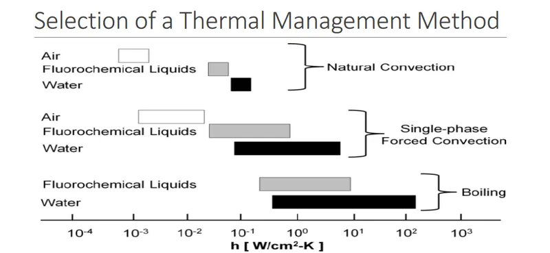
Depending on the convective heat transfer coefficient (h) of the material. We can choose a specific cooling system for our battery pack . Assuming pack temperature needs to be maintained at 45C with ambient temperature is of 35C with heat generation of 62W.First we need to calculate thermal resistance Rth =(∆T/Q) ((45-35)/62)which is 0.16K/W.
As we know Convective Thermal resistance is also equal (1/hA), so by equating 0.16 to the current formulae we get a value of 3.7*10^-2. so the suitable cooling system for the battery pack is forced convective air transfer.
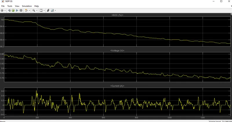
MATLAB RESULT
A Matlab analysis was done with the following configuration and the results were generated.