Project 1 - Interfacing a 16*2 LCD with Arduino using I2C protocol
answer:
In this digital age, we come across LCDs all around us from simple calculators to smartphones, computers and television sets, etc. The LCDs use liquid crystals to produce images or texts and are divided into different categories based on different criteria like type of manufacturing, monochrome or colour, and weather Graphical or character LCD. In this tutorial, we will be talking about the 16X2 character LCD Modules.
The 16x2 LCDs are very popular among the DIY community. Not only that, but you can also find them in many laboratory and industrial equipment. It can display up to 32 characters at a time. Each character segment is made up of 40 pixels that are arranged in a 5x8 matrix. We can create alphanumeric characters and custom characters by activating the corresponding pixels. Here is a vector representation of a 16x2 LCD, in which you can see those individual pixels.
16x2 LCD Module Pinout
The 16x2 has a 16-pin connector. The module can be used either in 4-bit mode or in 8-bit mode. In 4-bit mode, 4 of the data pins are not used and in 8-bit mode, all the pins are used. And the connections are as follows:
16x2 LCD Module – Parts
The 16x2 LCD modules are popular among the DIY community since they are cheap, easy to use and most importantly enable us to provide information very efficiently. With just 6 pins, we can display a lot of data on the display.
How to Control 16x2 LCD Module
Controlling the LCD module is pretty simple. Let’s walk through those steps. To adjust the contrast of the LCD, the Vo/ VEE pin is connected to a variable resistor. By adjusting the variable resistor, we can change the LCD contrast.
How to Test the 16X2 LCD Module
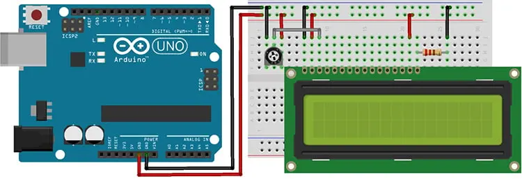
To test the LCD module, connect the VDD, GND, and backlight pins to 5v and GND. Connect the center terminal of a 10K variable resistor to the VEE pin. Connect the other two terminals to VCC and GND as per the below connection diagram-
Interfacing 16x2 LCD with Arduino
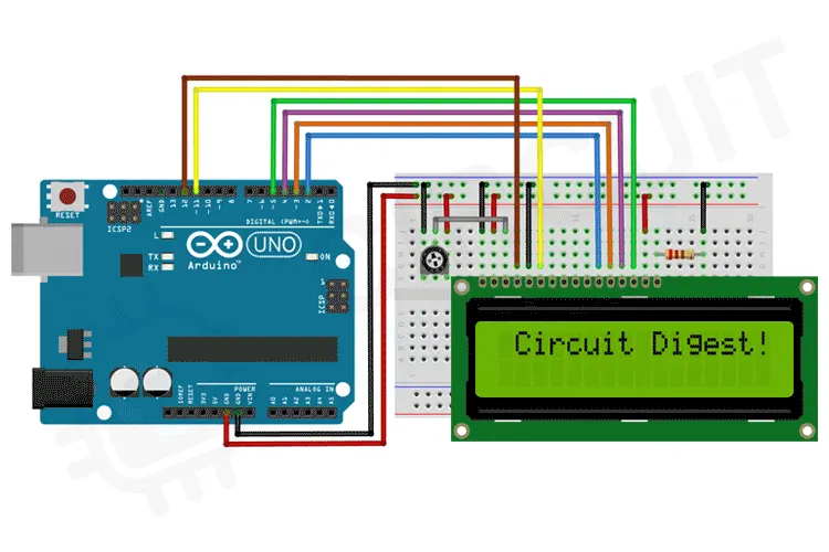
Let’s see how to connect the LCD module to Arduino. For that first, connect the VSS to the GND and VDD to the 5V. To use the LCD backlight, connect the backlight Anode to the 5V and connect the backlight cathode to the GND through a 220Ωresistor. Since we are not using the read function connect the LCD R/W pin to the GND too. To adjust the contrast, connect the centre pin of a 10KΩ trimmer resistor to the VEE pin and connect the side pins to the VCC and GND. Now connect the registry select pin to D12 and Enable pin to D11.Now let’s connect the data pins. The LCD module can work in two modes, 8-bit and 4-bit. 8-bit mode is faster but it will need 8 pins for data transfer. In 4-bit mode, we only need four pins for data. But it is slower since the data is sent one nibble at a time. 4-bit mode is often used to save I/O pins, while the 8-bit mode is used when speed is necessary. For this tutorial, we will be using the 4-bit mode. For that connect the D4, D5, D6 and D7 pins from the LCD to the D5, D4, D3 and D2 pins of the Arduino.
Here is the actual circuit. It is built as per the connection diagram provided. All the connections are made using standard male to male jumper wires.
Arduino Code to Interface 16x2 LCD
#include
const int rs = 12, en = 11, d4 = 2, d5 = 3, d6 = 4, d7 = 5;
LiquidCrystal lcd(rs, en, d4, d5, d6, d7);
void setup()
{
// set up the LCD's number of columns and rows:
lcd.begin(16, 2);
// Print a message to the LCD.
lcd.print(" Circuit Digest!");
delay(2000);
for (int positionCounter = 0; positionCounter < 16>
{
// wait a bit: delay(150);
}
lcd.clear();
lcd.setCursor(6, 0);
lcd.print("Count!");
// print the number of seconds since reset:
}
void loop()
{
for (int i = 0; i < 10>
{
lcd.setCursor(8, 1);
// print the number of seconds since reset: lcd.print(i);
delay(1000);
}
}
16x2 LCD Module Problems and Troubleshooting Steps
- Wrong characters are displayed: This problem occurs usually when the LCD is not getting the correct data. Make sure you are sending the correct ASCII value. If you are sending the correct ASCII characters, but still showing the wrong one on the LCD, check your connections for loose contact or short circuits.
- Display shows Black boxes or does not show anything: First thing to do in these situations is to adjust the contrast voltage by rotating the variable resistor. This will correct the contrast value and will give you a visible readout.
- Contrast is Ok, but still no display: Make sure to provide a sufficient time delay in between sending each character. Because if you don’t give enough time to process the data the display will malfunction.
- Contrast and delay are ok, but still no display: Make sure you are powering the LCD from a 5V source. By default, these displays won’t work with a supply voltage below 5V. So if you are using the display with a 3.3V microcontroller make sure to power the display from 5V and use level shifters in between the display and the microcontroller.