Project 1 - Interfacing a 16*2 LCD with Arduino using I2C protocol
Project 1 - Interfacing a 16*2 LCD with Arduino using I2C protocol
Overview of the Project:
In this project implementing the Code for “Interfacing a 16*2 LCD with two Arduino’s (one for Master and one for Slave) using Inter-Integrated Circuit (I2C) communication protocol” by sending the message to LCD using I2C communication protocol and display the message on LCD screen.
Goals:
- Communication between Arduino and 16*2 LCD using I2C protocol.
- Displaying the message sent by Master and received by slave i.e. LCD display
BASICS OF THE I2C COMMUNICATION PROTOCOL
INTRODUCTION TO I2C COMMUNICATION
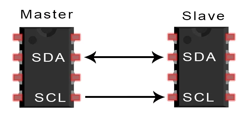
I2C combines the best features of SPI and UARTs. With I2C, you can connect multiple slaves to a single master (like SPI) and you can have multiple masters controlling single, or multiple slaves. This is really useful when you want to have more than one microcontroller logging data to a single memory card or displaying text to a single LCD.Like UART communication, I2C only uses two wires to transmit data between devices:
SDA (Serial Data) – The line for the master and slave to send and receive data.
SCL (Serial Clock) – The line that carries the clock signal.
HOW I2C WORKS
With I2C, data is transferred in messages. Messages are broken up into frames of data. Each message has an address frame that contains the binary address of the slave, and one or more data frames that contain the data being transmitted. The message also includes start and stop conditions, read/write bits, and ACK/NACK bits between each data frame:
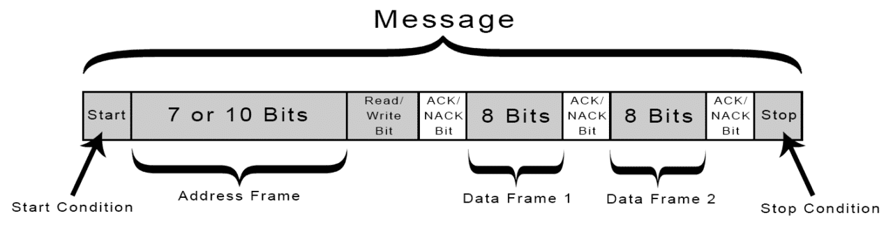
Start Condition: The SDA line switches from a high voltage level to a low voltage level before the SCL line switches from high to low.
Stop Condition: The SDA line switches from a low voltage level to a high voltage level after the SCL line switches from low to high.
Address Frame: A 7 or 10 bit sequence unique to each slave that identifies the slave when the master wants to talk to it.
Read/Write Bit: A single bit specifying whether the master is sending data to the slave (low voltage level) or requesting data from it (high voltage level
STEPS OF I2C DATA TRANSMISSION
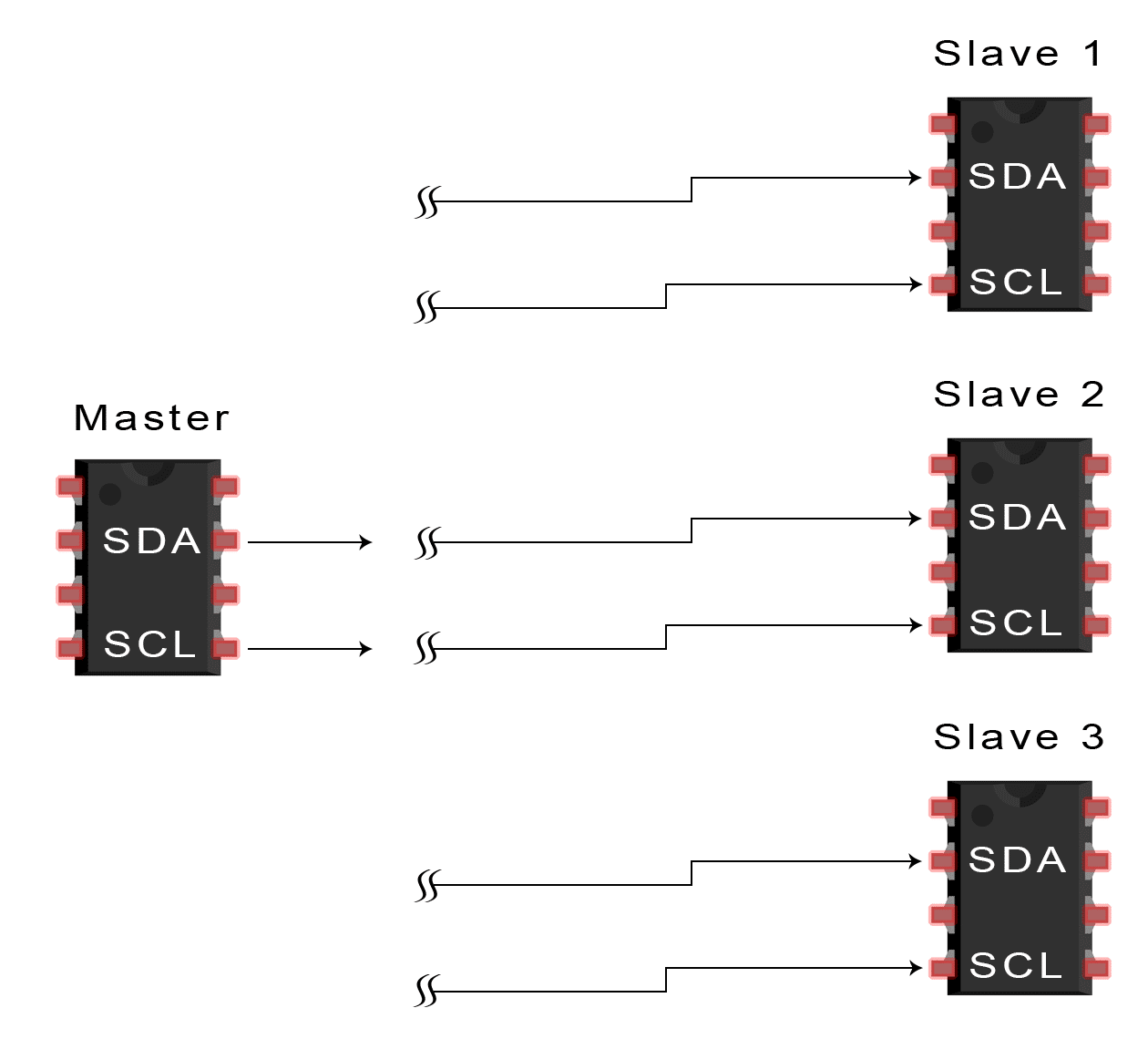
1. The master sends the start condition to every connected slave by switching the SDA line from a high voltage level to a low voltage level before switching the SCL line from high to low:
2. The master sends each slave the 7 or 10 bit address of the slave it wants to communicate with, along with the read/write bit:
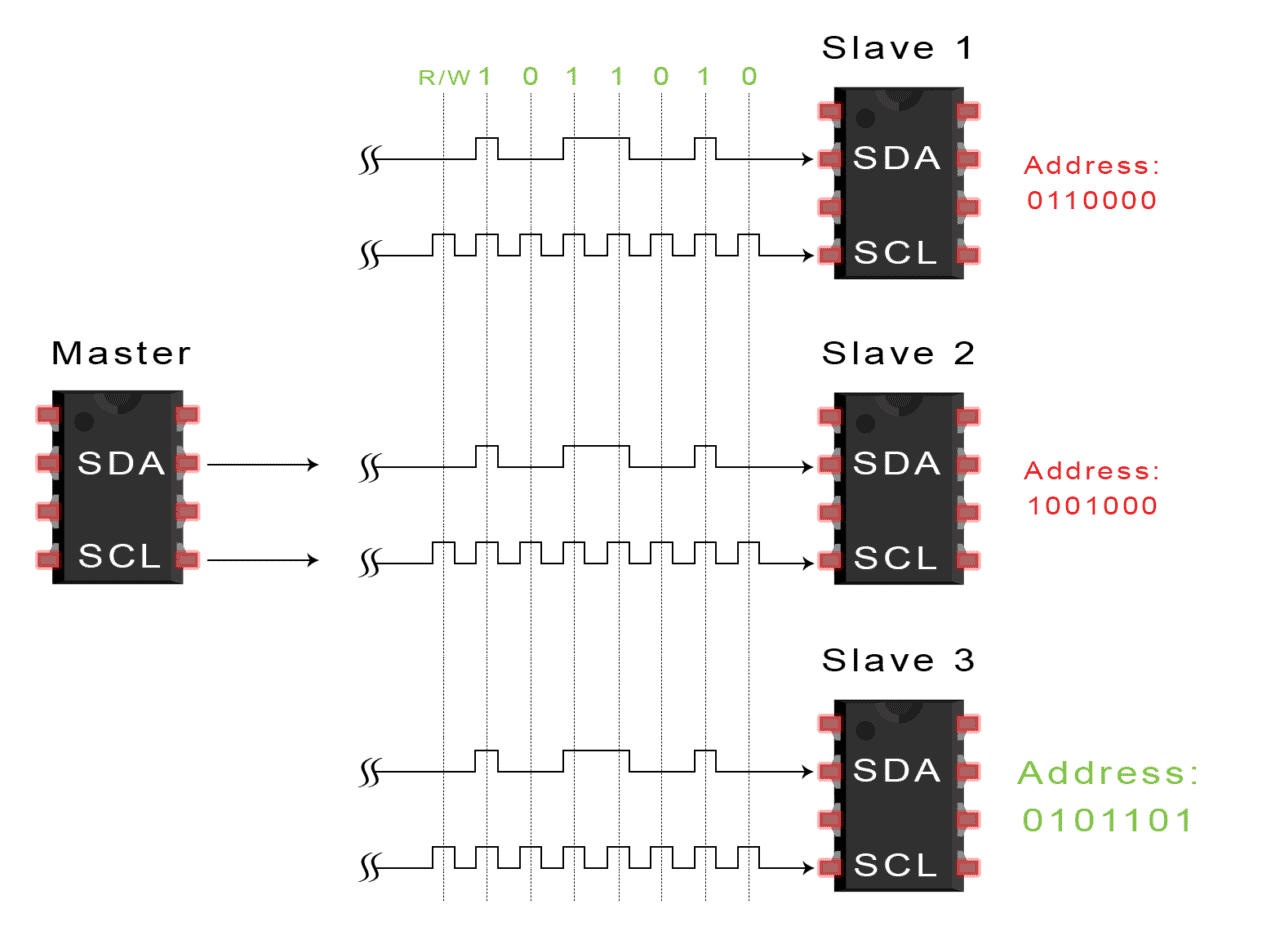
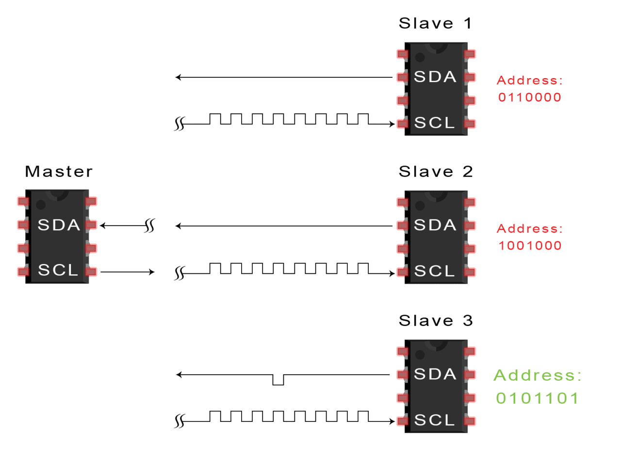
3. Each slave compares the address sent from the master to its own address. If the address matches, the slave returns an ACK bit by pulling the SDA line low for one bit. If the address from the master does not match the slave’s own address, the slave leaves the SDA line high.
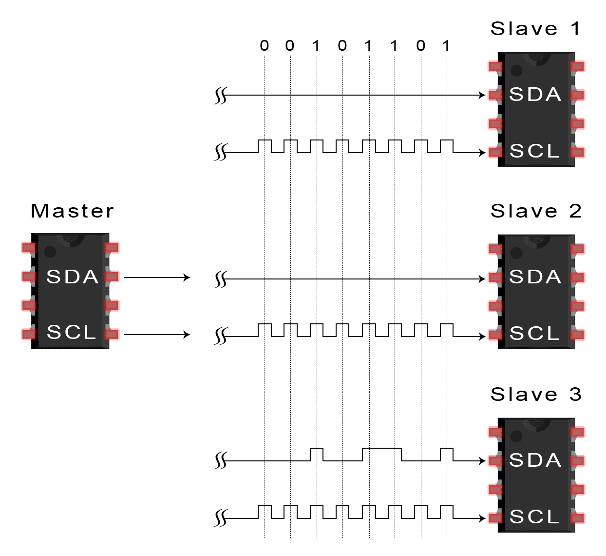
4. The master sends or receives the data frame:
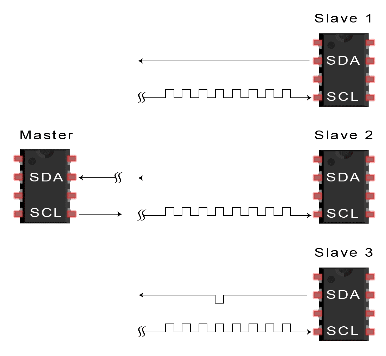
5. After each data frame has been transferred, the receiving device returns another ACK bit to the sender to acknowledge successful receipt of the frame:
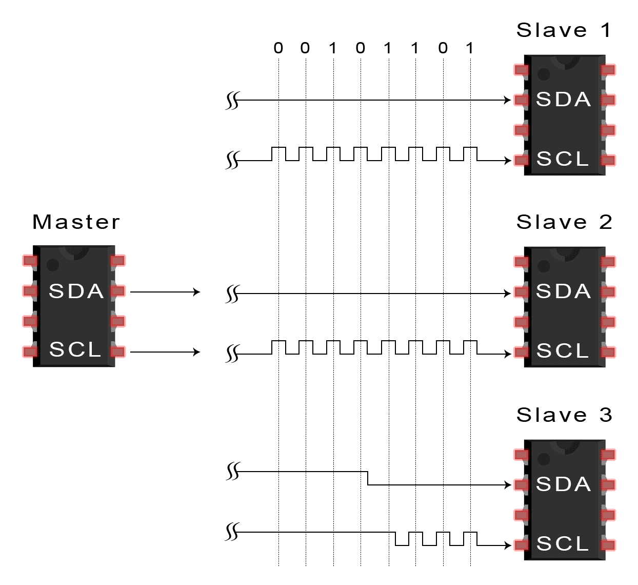
6. To stop the data transmission, the master sends a stop condition to the slave by switching SCL high before switching SDA high:
SINGLE MASTER WITH MULTIPLE SLAVES
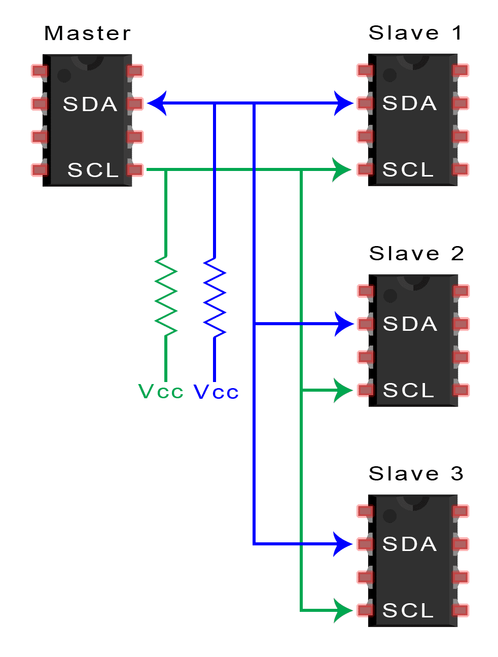
Because I2C uses addressing, multiple slaves can be controlled from a single master. With a 7 bit address, 128 (27) unique address are available. Using 10 bit addresses is uncommon, but provides 1,024 (210) unique addresses. To connect multiple slaves to a single master, wire them like this, with 4.7K Ohm pull-up resistors connecting the SDA and SCL lines to Vcc:
MULTIPLE MASTERS WITH MULTIPLE SLAVES
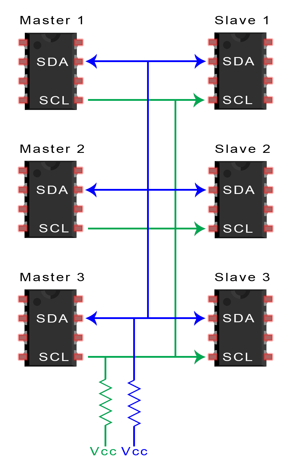
Multiple masters can be connected to a single slave or multiple slaves. The problem with multiple masters in the same system comes when two masters try to send or receive data at the same time over the SDA line. To solve this problem, each master needs to detect if the SDA line is low or high before transmitting a message. If the SDA line is low, this means that another master has control of the bus, and the master should wait to send the message. If the SDA line is high, then it’s safe to transmit the message. To connect multiple masters to multiple slaves, use the following diagram, with 4.7K Ohm pull-up resistors connecting the SDA and SCL lines to Vcc:
ADVANTAGES AND DISADVANTAGES OF I2C
There is a lot to I2C that might make it sound complicated compared to other protocols, but there are some good reasons why you may or may not want to use I2C to connect to a particular device:
ADVANTAGES
- Only uses two wires
- Supports multiple masters and multiple slaves
- ACK/NACK bit gives confirmation that each frame is transferred successfully
- Hardware is less complicated than with UARTs
- Well known and widely used protocol
DISADVANTAGES
- Slower data transfer rate than SPI
- The size of the data frame is limited to 8 bits
- More complicated hardware needed to implement than SPI
LIST OF COMPONENTS USED :
1.Arduino UNO R3 - 2Nos
2. LCD 16*2 - 2 NOS
3. POTENTIO METER - 2 NOS
4. BREAD BOARD- 2 NOS
CODING DETAILS:
MASTER CODE:
#include
const int rs=12, en=11, d4=4, d5=5, d6=6, d7=7;
LiquidCrystal lcd(rs, en, d4, d5, d6, d7); // Define LCD MODULE PINS
int val1=A4;
int val2=A5;
void setup()
{
lcd.begin(16,2);
}
void loop()
{
{
for(int positionCounter =1; positionCounter++;)
{
lcd.scrollDisplayRight();
lcd.setCursor(0,0); // SETS CURSOR AT LINE ONE OF LCD
lcd.print(">> slave<<"); //PRINTS LCD
lcd.setCursor(0,1); //SETS CURSOR AT LINE ONE OF LCD
lcd.print("masterVal:100");// PRINTS LCD
delay(5000);
}
}
}
SLAVE CODE:
#include
const int rs=12, en=11, d4=4, d5=5, d6=6, d7=7;
LiquidCrystal lcd(rs, en, d4, d5, d6, d7); // Define LCD MODULE PINS
int val1=A4;
int val2=A5;
void setup()
{
lcd.begin(16,2);
}
void loop()
{
{
for(int positionCounter =1; positionCounter++;)
{
lcd.scrollDisplayRight();
lcd.setCursor(0,0); // SETS CURSOR AT LINE ONE OF LCD
lcd.print(">> master<<"); // PRINTS LCD
lcd.setCursor(0,1); //SETS CURSOR AT LINE ONE OF LCD
lcd.print("slaveVal:99"); // PRINTS LCD
delay(5000);
}
}
}