Project 1 - Interfacing a 16*2 LCD with Arduino using I2C protocol
Project 1 - Interfacing a 16*2 LCD with Arduino using I2C protocol
Overview of the Project:
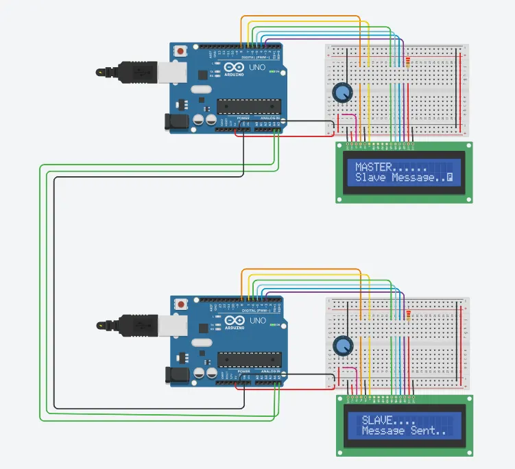
In this project implementing the Code for “Interfacing a 16*2 LCD with two Arduino’s (one for Master and one for Slave) using Inter-Integrated Circuit (I2C) communication protocol” by sending the message to LCD using I2C communication protocol and display the message on LCD screen.
Goals:
- Communication between Arduino and 16*2 LCD using I2C protocol.
- Displaying the message sent by Master and received by slave i.e. LCD display.
Key Highlights of the Project:
- Using the inter-integrated circuit communication protocol, transferring the data i.e. the message we want to display is sent to the LCD.
- Two Arduino’s connected to the LCD display and the communication is executed using I2C protocol between Arduino and the LDC display.
Deliverables of this project:
- Communication between the Arduino’s and LCD using I2C.
- The message passed from master to slave and displayed on the 16*2 LCD.
Expected Outcomes:
- Students will get the Knowledge of I2C communication Protocol and the Arduino.
- The Hardware connection of all components used in this project.
- Displaying the message sent by master (Arduino) and received by the slave (16*2 LCD display).
I2C Communication Protocol :-
I2C or I2C is short for Inter-Integrated Circuit, a synchronous serial communication protocol developed by Phillips for communication between a fast Microcontroller and relatively slow peripherals (like Memory or Sensors) using just two wires. Hence, it is sometimes also known as TWI (Two Wire Interface).
Using I2C, you can transmit data at rates 100 kbit/s (clock 100 kHz – Standard Mode), 400 kbit/s (clock 400 kHz – Fast Mode), 1 Mbit/s (clock 1 MHz – Fast Mode Plus) and 3.4 Mbit/s (clock 3.4 MHz – High Speed Mode).
This may not seem much but it is sufficient for interfacing sensors, memories and displays at small distances.
I2C Bus :-
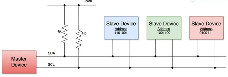
The I2C Bus consists of two wires called the Serial Data (SDA) and the Serial Clock (SCL). Data is transmitted through the SDA line while the SCL line is used to synchronize the devices with the clock signal.
Both these bus lines are open-drain drivers and hence you have to use pull-up resistors to keep them HIGH.
There are two types of devices that connect to the I2C Bus: Master and Slave. Bus Masters are responsible for sending and receiving data to and from the slave devices. The clock signal is also supplied by the master.
I2C network supports multiple masters and multiple slaves (but we usually see single master and multiple slaves). Each slave device connected to the I2C bus has a unique 7-bit address.
Using this address, master selects a particular slave for data transmission (send or receive) and the selected slave responds according to request.
I2C in Arduino :-
Arduino supports I2C Communication. If you take a look at the pinout of Arduino UNO . Analog Input pins A4 and A5 have an alternative function of I2C.
The A4 pin acts as SDA while the A5 pin acts as SCL. In R3 of original Arduino UNO, there are two more pins near Digital IO Pin 13 (near the USB socket), dedicated to SDA and SCL.
For interfacing a 16*2 LCD with Arduino using I2C protocol we will need :-
Components Required :-
- Arduino UNO x 2
- LCD 16x2 x 2
- 220 Ω Resistor x 2
- 250 kΩ Potentiometer x 2
- Breadboard
- Connecting Wires
Schematic View :-
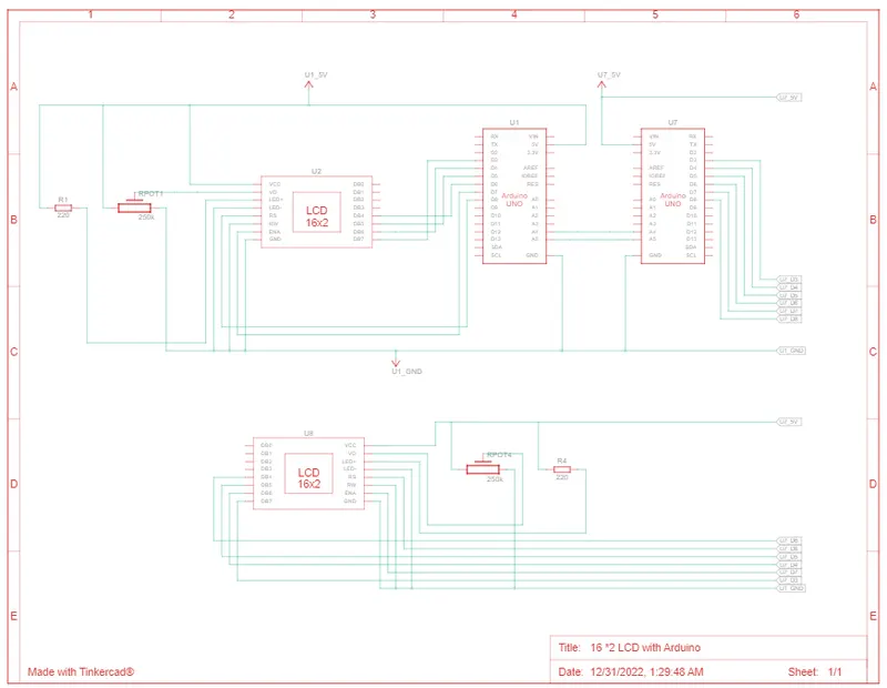
Circuit Diagram :-
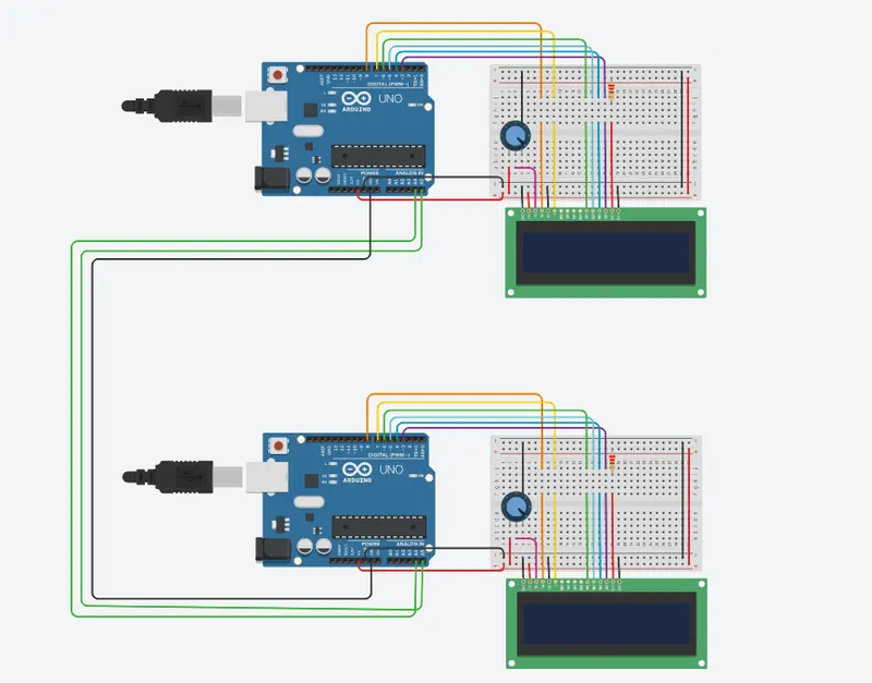
Code :-
We are Including two Libraries
- Wire Library Functions
To use this library:
#include <Wire.h>
Wire Library which provides 10 functions for developing I2C related applications. They are:
- Wire.begin()
- Wire.requestFrom()
- Wire.beginTransmission()
- Wire.endTransmission()
- Wire.write()
- Wire.available()
- Wire.read()
- Wire.SetClock()
- Wire.onReceive()
- Wire.onRequest()
2. LiquidCrystal Library Functions :-
This library allows an Arduino board to control LiquidCrystal displays (LCDs) based on the Hitachi HD44780 (or a compatible) chipset, which is found on most text-based LCDs. The library works with in either 4- or 8-bit mode (i.e. using 4 or 8 data lines in addition to the rs, enable, and, optionally, the rw control lines).
To use this library:
#include <LiquidCrystal.h>
Functions
Master Code:-
// include the library code:
#include <LiquidCrystal.h>
#include <Wire.h>
// initialize the library with the numbers of the interface pins
LiquidCrystal lcd(8, 7, 6, 5, 4, 3);
char MasterReceive[16]; //String to get the message
void setup()
{
Serial.begin(9600);
Wire.begin(); // To begin I2C Communication
lcd.begin(16, 2); // lcd starts with resolution 16x2
lcd.clear();
}
void loop()
{
Wire.requestFrom(8,16); //8-address,16-characters
lcd.setCursor(0,0);
lcd.print("MASTER......");
lcd.setCursor(0,1);
int i=0;
while(0<Wire.available()) //check the number of bytes available
{
MasterReceive[i]=Wire.read(); //print character by character
i++;
}
lcd.print(MasterReceive);
delay(1000);
Wire.end();
}
Slave Code :-
// include the library code:
#include <LiquidCrystal.h>
#include <Wire.h>
// initialize the library with the numbers of the interface pins
LiquidCrystal lcd(8, 7, 6, 5, 4, 3);
void setup()
{
Serial.begin(9600);
Wire.begin(8); // To begin I2C Communication
Wire.onRequest(send); //call send fuction
lcd.begin(16, 2); // lcd starts with resolution 16x2
lcd.clear();
}
void loop()
{
lcd.setCursor(0,0);
lcd.print(" SLAVE....");
lcd.setCursor(0,1);
lcd.print(" Message Sent..");
}
void send()
{
char ch[17]="Slave Message.."; //creating string
Wire.write(ch); //to send message to master
}
Output :-