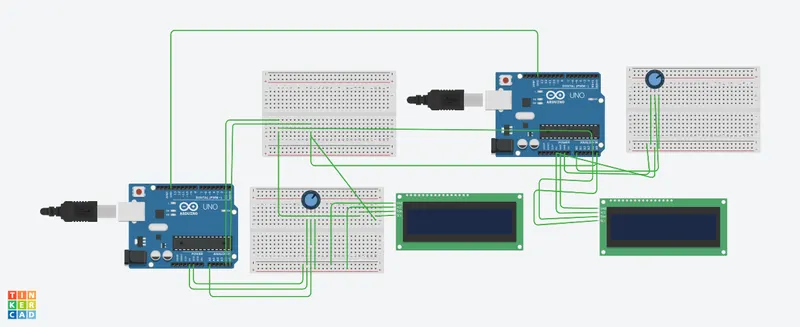
Project 1 - Interfacing a 16*2 LCD with Arduino using I2C protocol
Aim: Interfacing two lcd display using I2C protocol.
Goals:
- Communication between Arduino and 16*2 LCD using I2C protocol.
- Displaying the message sent by Master and received by slave i.e. LCD display.
I2C Communication(Inter-Integrated Communication)
I2C is a serial protocol used on a low-speed 2-wire interface. It was originally developed by Phillips in 1982 to allow integrated circuits within television receivers to communicate with one another.
I2C is an abbreviation for “Inter-Integrated Circuit”. It is also called “IIC” or ‘I squared C”
I2C is used with microcontrollers like the Arduino and with microcomputers like the Raspberry Pi. Many displays and sensors interface to their host controller using I2C.I2C does have several limitations however. It is not particularly fast, although for most of its intended uses it is plenty fast enough.I2C can only be used over short distances, after all, it was originally meant to communicate between integrated circuits on the same printed circuit board. The maximum distance of reliable transmission decreases as the speed increases, at the slowest speed (100 Kbaud or a clock rate of 100 KHz) the maximum distance is about a metre.
I2C speed
The original I2C bus had a maximum speed of 100 KHz. Most common applications still use this speed, as it is quite sufficient for transferring data from sensors and to simple displays.
I2C and has some higher speed modes. Not all I2C devices support these modes:
- Fast Mode – This has a maximum clock speed of 400 KHz.
- Hi-Speed Mode – A maximum clock frequency fo 3.4 MHz
- Ultra Fast Mode – Maximum clock frequency of 5 MHz
On an I2C bus it is the master that determines the clock speed.
I2C Working
An I2C bus has two signals, along with a power and ground connection.
The two signal lines are as follows:
- SDA – This is the bidirectional data line.
- SCL – This is the clock signal.
There are two pull-up resistors attached to each signal line, they pull the bus up to the supply voltage when it is inactive.The supply voltage is not standard, it can be either 3.3 or 5-volts. It can also be a lower voltage for some high-speed I2C implementations.This difference in supply voltages can cause issues when you are interfacing I2C devices that use different logic levels.
There are two types of devices that can be interfaced to the I2C bus – Masters and Slaves.
The Master device controls the bus and supplies the clock signal. It requests data from the slaves individually. There can be more than one master device on the bus but only one can be the active master at any given moment.The master devices do not have an address assigned to them.
Slave devices do have an address, and this address needs to be unique on the bus. They use a 7-bit addressing scheme, so up to 128 slaves can be on one I2C bus. In real life this large collection of devices is never used, it is rare to see over a dozen I2C devices on one bus.
Arduino Wire Library
The Arduino has a built-in library for working with I2C called the Wire Library. It makes it very easy to communicate on the I2C bus, and it can configure the Arduino to become either a master or a slave.
The Wire library has several useful functions for working with I2C.
The Wire library has several useful functions for working with I2C.
- begin – This initiates the library and sets up the Arduino to be either master or slave.
- requestfrom – This function is used by the master to request data from a slave.
- beginTransmission – This function is used by the master to send data to a specified slave.
- endTransmissiom – This function is used by the master to end a transmission started with the beginTransmission function.
- write– Used by both master and slave to send data on the I2C bus.
- available - Used by both master and slave to determine the number of bytes in the data they are receiving.
- read – Reads a byte of data from the I2C bus.
- SetClock – Used by the master to set a specific clock frequency.
- onReceive – Used by the slave to specify a function that is called when data is received from the master.
- onRequest– Used by the slave to specify a function that is called when the master has requested data.
Code for master
// C++ code
//MASTER CODE
#include <Wire.h>
#include <LiquidCrystal_I2C.h>
// Master code
//
LiquidCrystal_I2C lcd(32, 16, 2);
void setup()
{
lcd.init();
lcd.begin(16,2);
lcd.backlight();
lcd.setCursor(0,0);
lcd.print("Master DEVICE");
lcd.setCursor(0,1);
lcd.print("is ON!");
delay(5000);
lcd.clear();
Serial.begin(9600);
Wire.begin();//Master Mode
}
void loop()
{
Wire.requestFrom(9,1); // request 1 byte of data from slave
byte MasterReceive = Wire.read();
int potvalue = analogRead(A0);
byte MasterSend = map(potvalue,0,1023,0,127);
Wire.beginTransmission(9);
Wire.write(MasterSend);
Wire.endTransmission();
lcd.setCursor(0,0);
lcd.print("MASTER");
lcd.setCursor(0,1);
lcd.print("SLAVE VAL: ");
lcd.print(MasterReceive);
Serial.println("Master data recived from slave");
Serial.println(MasterReceive);
}
Code for Slave:
#include <Wire.h>
#include <LiquidCrystal_I2C.h>
// C++ code
//SLAVE_device
LiquidCrystal_I2C lcd(39, 16, 2);
byte slave_rcv = 0;
void setup()
{
lcd.init();
lcd.begin(16,2);
lcd.backlight();
lcd.setCursor(0,0);
lcd.print("SLAVE DEVICE");
lcd.setCursor(0,1);
lcd.print("is ON!");
delay(5000);
lcd.clear();
Serial.begin(9600);
Wire.begin(9); //9 is the SLAVE ADDRESS
Wire.onReceive(receiveEvent);//IRQ
Wire.onRequest(requestEvent);//IRQ
}
void loop()
{
lcd.setCursor(0,0);
lcd.print("SLAVE DEVICE");
lcd.setCursor(0,1);
lcd.print("MASTERVALUE");
lcd.print(slave_rcv);
Serial.println("Slave Received from Master:");
Serial.println(slave_rcv);
delay(500);
lcd.clear();
}
void receiveEvent (int n) //Slave receives value from master
{
slave_rcv = Wire.read();
}
void requestEvent()
{
int potval = analogRead(A0);
byte SlaveSend = map(potval,0,1023,0,127);
Wire.write(SlaveSend);
}
LCD interfacing: