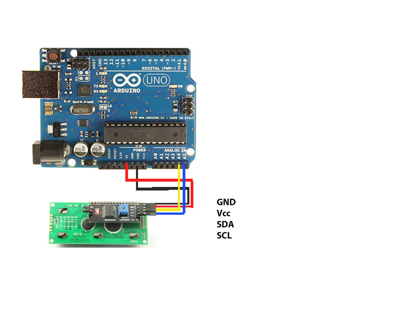
Project 1 - Interfacing a 16*2 LCD with Arduino using I2C protocol
I2C Communication
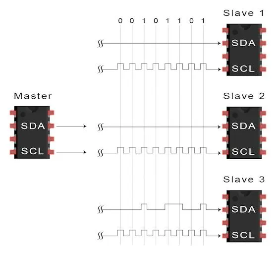
I2C is short for Inter-IC. And it is a type of BUS. This is designed by Philips semiconductors. I2C is a synchronous, multi slave, multi master packet switched, single-ended serial bus. ie. multiple chips can be connect to the same bus.I2C uses only two bidirectional open collector or open drain lines, Serial Data Line (SDA) and Serial Clock Line (SCL), pulled up with resistors.
I2C Serial Interface Adapter
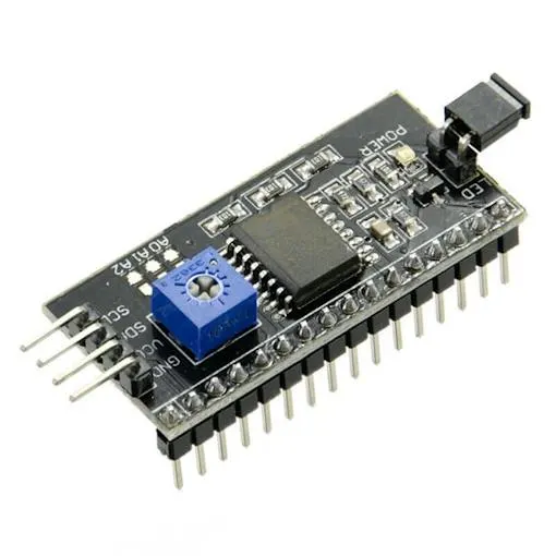
It is also known as I2C Module. It has total of 20 male pins. 16 pins are faced to rear side and 4 pins faced towards front side. The 16 pins for connect to 16x2 LCD and the 2 pins out of 4 pins are SDA and SCL. SDA is the serial data pin and SCL is the clock pin. The rest 2 pins for power supply (Vcc and ground).There is a POT on the I2C Module. We can control the contrast of the LCD display by rotating this POT. And there is a jumber fixed on the module. When we remove the jumber, the backlight of the LCD display will go OFF.
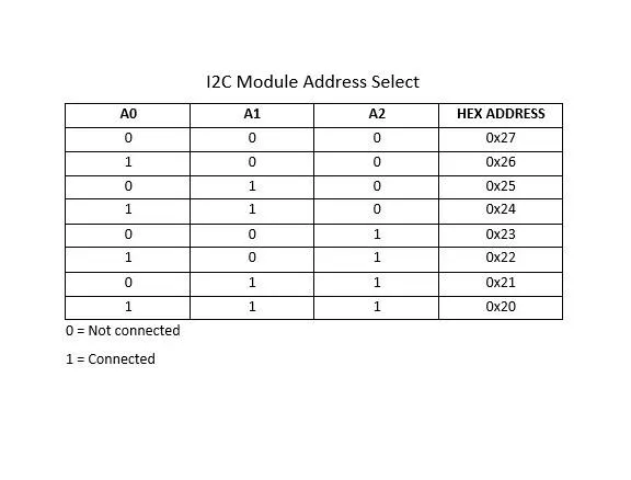
I2C Scanner Code
#include
void setup()
{
Wire.begin();
Serial.begin(9600);
Serial.println("\nI2C Scanner");
}
void loop()
{
byte error, address;
int Devices;
Serial.println("Scanning...");
Devices = 0;
for(address = 1; address < 127; address++ )
{

Wire.beginTransmission(address);
error = Wire.endTransmission();
if (error == 0)
{
Serial.print("I2C device found at address 0x");
if (address<16)
Serial.print("0");
Serial.print(address,HEX);
Serial.println("  !");
Devices++;
}
else if (error==4)
{
Serial.print("Unknown error at address 0x");
if (address<16)
Serial.print("0");
Serial.println(address,HEX);
}
}
if (Devices == 0)
Serial.println("No I2C devices found\n");
else
Serial.println("done\n");
delay(5000);
}
Arduino Uno I2C module
Analog Pin 4 - SDA
Analog pin 5 - SCL
5V - Vcc
GND - GND