Project 1 - Implement a fully functional Queue in C language using Linked lists
An IMU has two sensors:
- Accelerometer
- Gyroscope
Integrate the IMU to the development board; classify the data coming from Accelerometer and Gyroscope. Send the data of respective sensors on “Separate Queues” to a particular task. This task will identify which source is sending the data using “Queue Sets” and transfer the data to the respective UART Channe
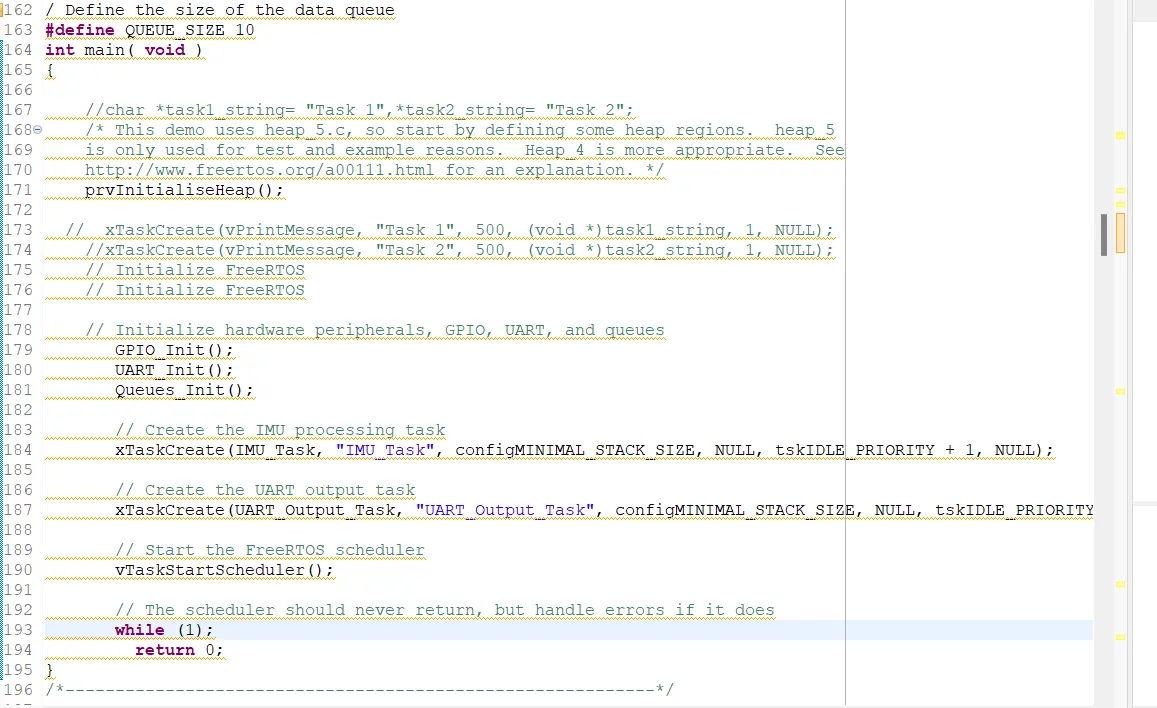
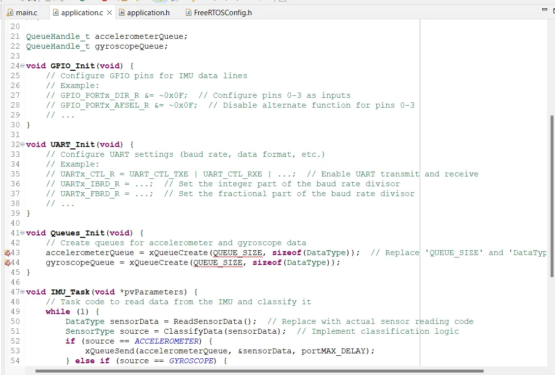
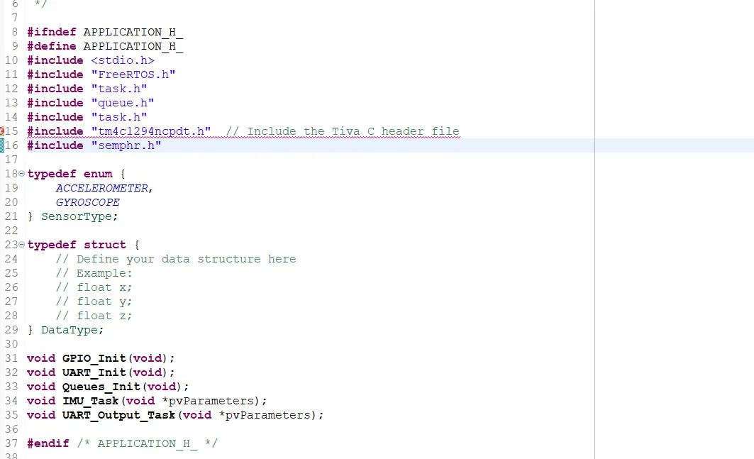
Key Learnings from the Project:
FreeRTOS: The program demonstrates the use of FreeRTOS, a real-time operating system, for multitasking on embedded systems. It shows how to create and manage tasks, use semaphores (mutex), and set up a task scheduler.
Microcontroller Hardware: It highlights the initialization and configuration of microcontroller hardware components such as GPIO and UART, which are essential for interfacing with sensors and peripherals.
Task Synchronization: The program showcases the use of semaphores (mutex) for task synchronization. Mutexes are used to protect shared resources, ensuring that only one task accesses them at a time.
Queue Communication: The program demonstrates the use of queues to facilitate inter-task communication. It uses separate queues to transmit data from the accelerometer and gyroscope sensors to a processing task.
Sensor Data Processing: It illustrates how to read data from sensors (in this case, an IMU with accelerometer and gyroscope) and classify the data based on its source.
UART Communication: The program sets up UART communication to send sensor data to an external interface, which can be a serial console or another device capable of receiving UART data.
Adaptation for Different Hardware: It emphasizes the need to adapt the code for specific hardware.
Important Commands and Libraries:
- FreeRTOS: FreeRTOS is the core library for real-time multitasking and task management.
- task.h: This library provides functions and macros for task creation and management.
- semphr.h: It includes functions and macros for semaphore management, which is crucial for task synchronization.
- queue.h: The library for creating and managing queues, which are used for inter-task communication.
- tm4c1294ncpdt.h: The Tiva C board-specific header file for hardware initialization and access to peripheral registers.
Tiva C Board is Suitable for FreeRTOS:
RTOS Support: The Tiva C series microcontrollers, including the TM4C1294NCPDT, are well-supported by FreeRTOS. FreeRTOS provides pre-configured project templates for Tiva C boards, making it easier to get started with real-time multitasking.
Abundant Peripherals: Tiva C boards come with a wide range of peripherals, including GPIO, UART, I2C, SPI, and more. This flexibility allows developers to interface with various sensors and devices.
Performance: Tiva C microcontrollers are known for their performance, making them suitable for real-time applications. They offer a high clock speed, multiple hardware interrupt sources, and sufficient RAM for running multiple tasks concurrently.
Community and Documentation: Tiva C series microcontrollers have an active user community and extensive documentation, which is valuable for troubleshooting and learning.
UART (Universal Asynchronous Receiver-Transmitter): UART is a serial communication protocol used for transmitting and receiving data between a microcontroller and external devices. In this program, UART is used to send sensor data to an external interface, such as a serial console. The UART_Init() function initializes the UART hardware, and the UART_Output_Task() function sends data to the UART channel.
GPIO :
GPIO (General-Purpose Input/Output) is used to configure and manage the digital pins on the microcontroller for interfacing with sensors and other peripherals. GPIO pins are versatile and can be used for both input and output operations, making them essential for interacting with external hardware.
Initialization: The
GPIO_Init()function is used to initialize GPIO pins. It does the following:- Enables the clock for a specific GPIO port on the Tiva C board.
- Waits for the clock signal to stabilize before proceeding.
Configuration: Within the
GPIO_Init()function, pins on the selected GPIO port are configured for input or output. Specifically, pins are configured as inputs to read data from external sensors.Reading GPIO Pins: Throughout the program, GPIO pins are read as input to obtain data from sensors. The program likely includes code to read the state of these pins, which could represent sensor measurements, and store that data for further processing.
Interaction with Sensors: The GPIO pins are used as data lines to communicate with sensors like the accelerometer and gyroscope. The specific pins on the GPIO port are used to receive data from these sensors.
Separate Queues: The program uses separate queues (accelerometerQueue and gyroscopeQueue) to manage data from the accelerometer and gyroscope sensors. Here's how it works:
- The IMU_Task() function reads sensor data from the accelerometer and gyroscope.
- It then classifies the data based on its source (accelerometer or gyroscope).
- If the data is from the accelerometer, it is sent to the accelerometerQueue using xQueueSend().
- If the data is from the gyroscope, it is sent to the gyroscopeQueue in a similar manner.
- Another task can wait on these queues to receive and process the sensor data separately.
Using separate queues ensures that data from different sensors is kept distinct and can be processed independently by other tasks. This separation of data allows for better organization and easier processing of sensor information in a real-world application.