Project 1 - Development of TFT Cluster Speedmeter Software Component
Project 1 - Development of TFT Cluster Speedmeter Software Component
Cluster Instrument receives the signals from other ECU's via CAN bus interface. It also receives commands from the driver via steering wheel buttons. The signals are then processed by the Cluster ECU, after which the Cluster ECU may send the vehicle information to the LCD or light the LEDs and so forth, according to the results. Therefore, the Cluster ECU can be viewed as a carrier of the information flow.
Key Highlights:
- Project covers contents from Week 3 to Week 10
- Objective of the project is to calculate the speed value which is getting displayed in the cluster unit
- Stages of development starts from Requirement Engineering to Model Development complying to JMAAB guidelines
- This is followed by Simulink Design Verifier – Design Verification stage.
- This is followed by writing functional test cases, MIL & SIL validation.
- Next is Simulink Design Verifier – Test Generation Criteria
- Next stage is Polyspace Static Code Analysis followed by test automation using Simulink Test Manager
Deliverables:
- Software Requirement Report (SwREQ document)
- Working Model with SLDD file
- Reports including JMAAB, Requirement Tagging report, SLDV reports & MIL – SIL Coverage Reports
- Auto - generated code
- MIL SIL Test Harness, Test Results & Functional Test Cases
- QA Static Code Analysis results
- Simulink Test Manager Results
CONTENTS:
- Modelling of TFT cluster speedmeter
- Requirement generation and report by requirement manager
- JMAAB guidelines for the model
- SLDV - Design verification for detecting design errors
- Functional Test case - MIL harness creation and MIL coverage report
- Code Generation - Functional Test case - SIL harness creation and SIL coverage report
- SLDV - Test Generation
- PolySpace static code Analysis
- Simulink Test Manager - Baseline Testing and Back to back testing results and reports.
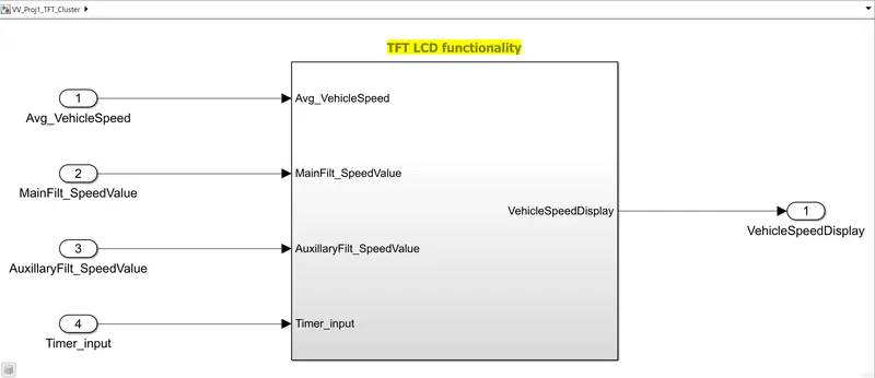
Modelling of TFT cluster speedmeter:
The overall model looks like:
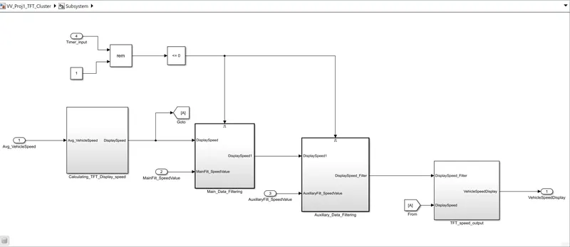
Subsystems of overall model:
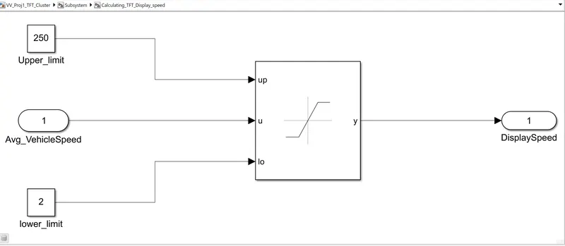
Subsystem: Calculating_TFT_Display_speed
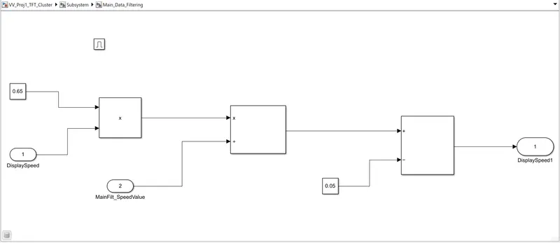
Subsystem: Main_Data_Filtering
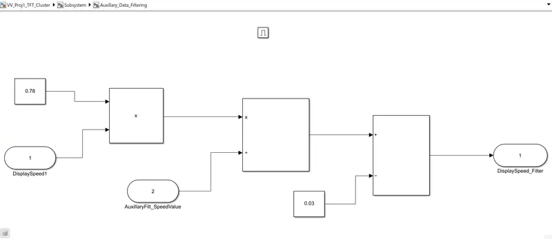
Subsystem: Auxillary_Data_Filtering
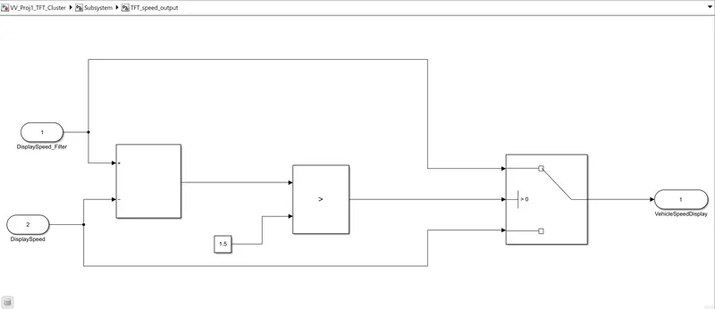
Subsystem: TFT_speed_output
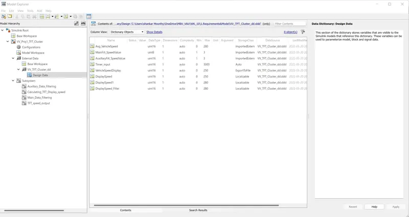
The SLDD is linked and it is shown below:
Requirement generation and report by requirement manager
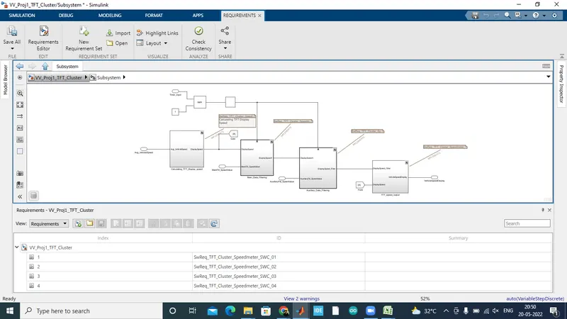
The requirement is linked and the image shown below:
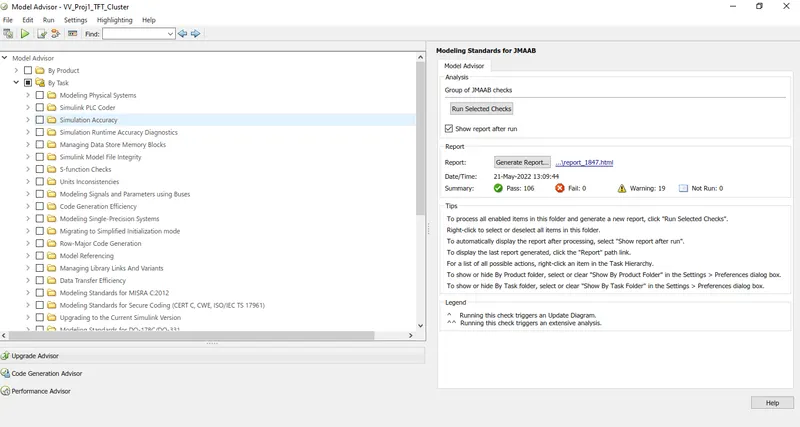
JMAAB guidelines for the model
SLDV - Design verification for detecting design errors:
SLDV - Design error detection is done and the corresponding report is generated.
Functional Test case - MIL harness creation and MIL coverage report:
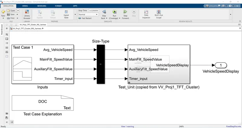
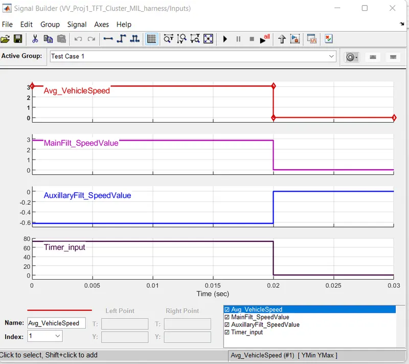
Function test cases and MIL harness is created and the screenshots are attached below:
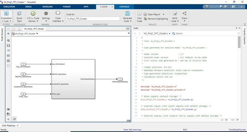
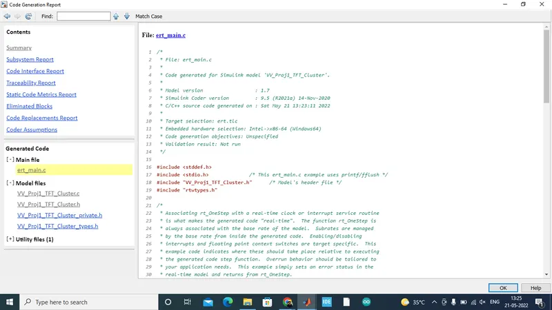
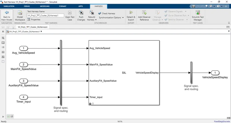
Code Generation - Functional Test case - SIL harness creation and SIL coverage report:
SLDV - Test Generation:
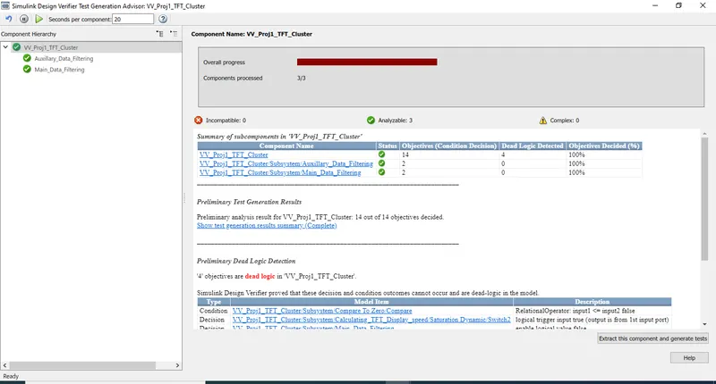
The advisor report for the SLDV - Test generation is below:
PolySpace static code Analysis:
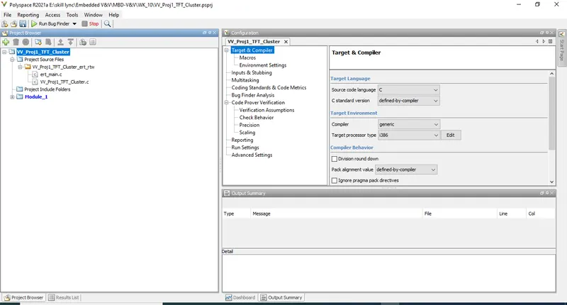
The polyspace static code analysis is done and the image is shown below:
Simulink Test Manager - Baseline Testing and Back to back testing results and reports:
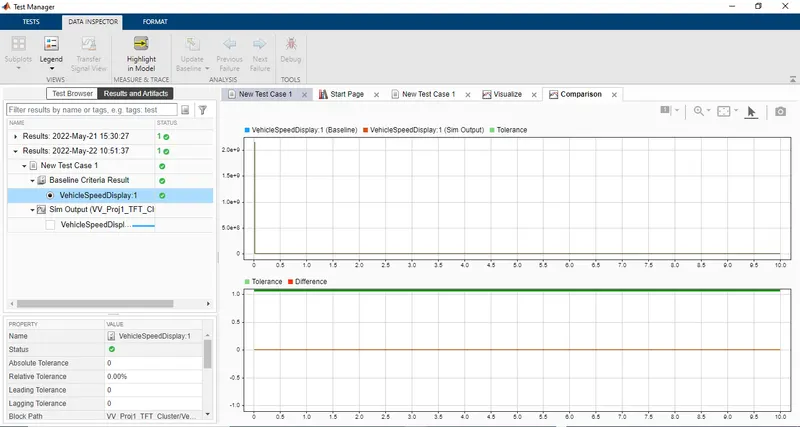
Using Simulink Test manager, Baseline testing is done and MIL results are compared and reports are generated as shown below:
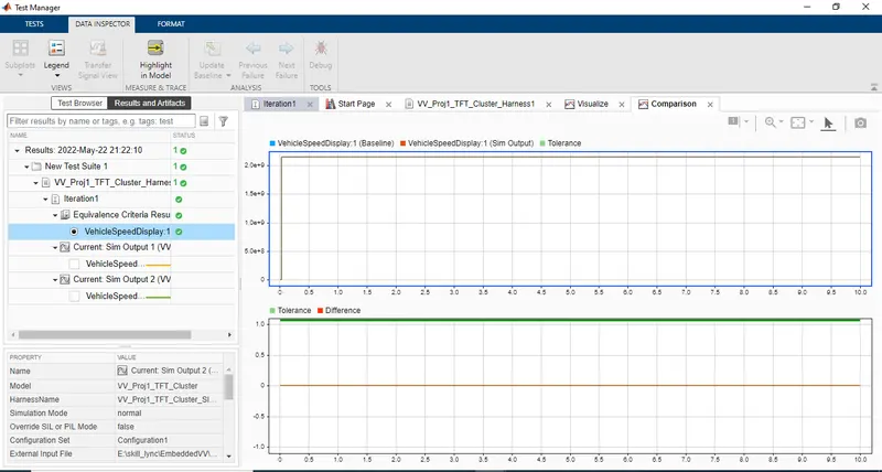
Using Simulink Test manager, Back to back testing is done and SIL results are compared and reports are generated as shown below:
Thus all the Verification and validation process are performed from requirement till simulink Test.
ATTACHMENTS CONTAINS:
- .SLX file, sldd file,Slreq file.
- Requirement tag report
- JMAAB - model advisor report
- SLDV - Design error detection report
- MIL harness model and MIL coverage report
- SLDV - Test generation report
- Generated code file
- SIL harness and SIL coverage report
- Simulink Test - Basline test report and Back to back test report.