Project 1 _Creating an Architectural plan for the provided plot size and develop relevant basic structural drawings
AIM :
To draw residential building of dimensions 60' x 20' with the following drawings
1) ARCHITECTURAL DRAWING
PLOT DRAWING
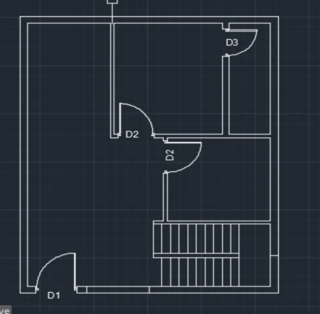
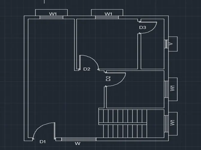
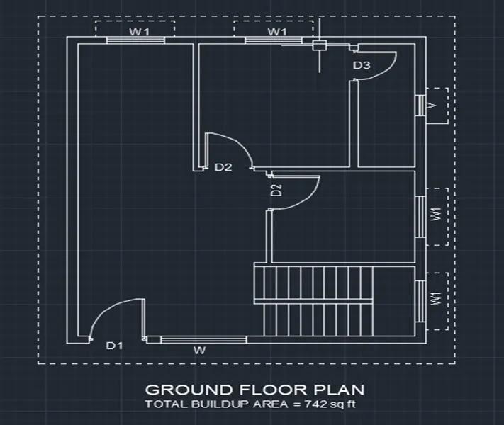
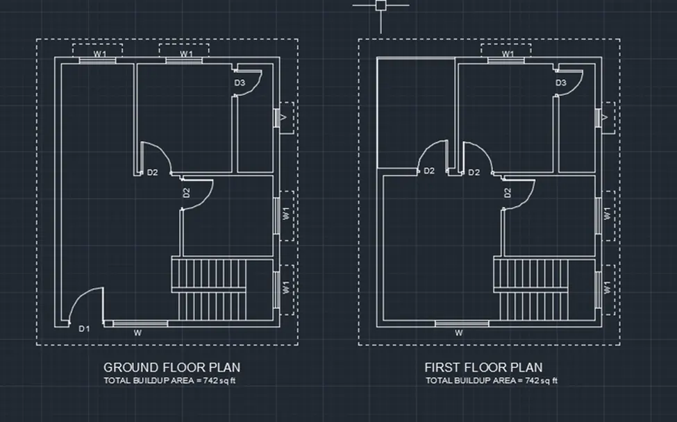
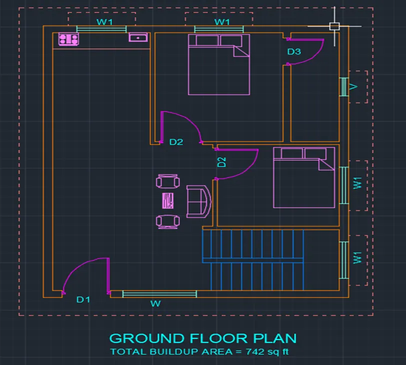
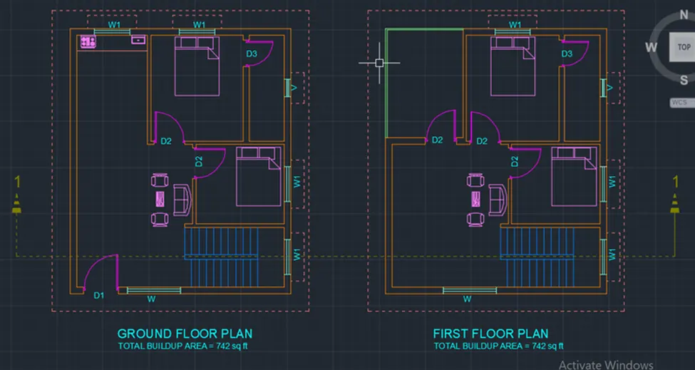
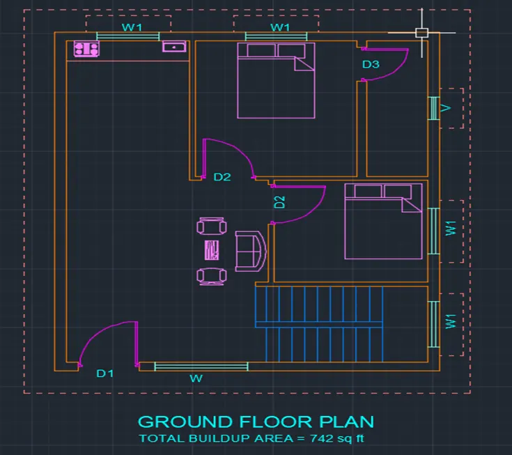
GROUND FLOOR PLAN
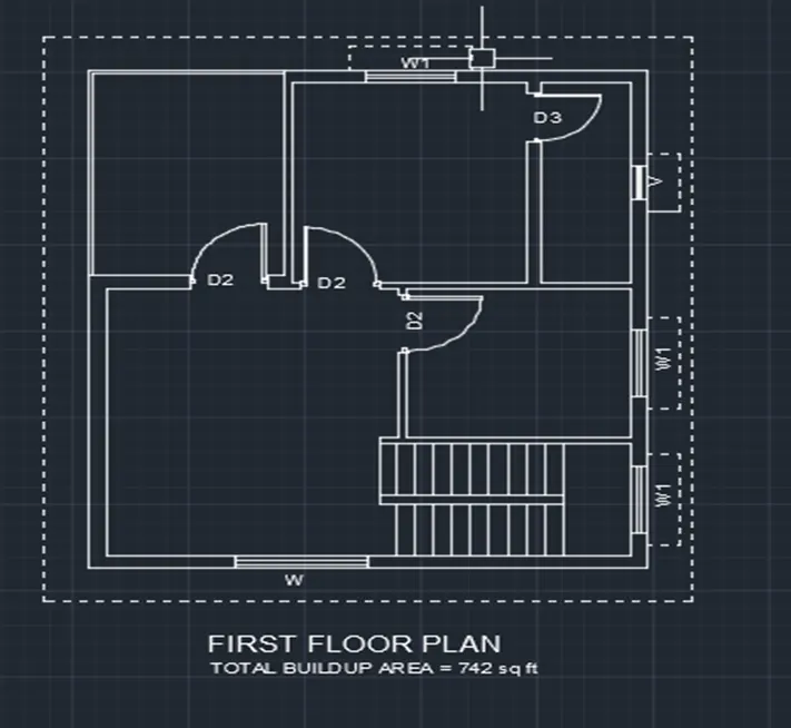
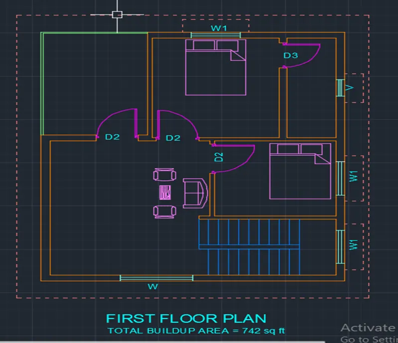
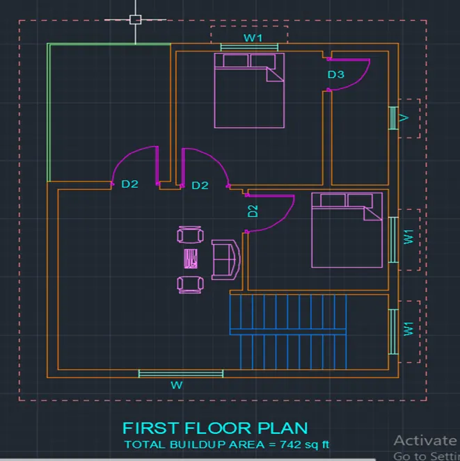
FIRST FLOOR PLAN
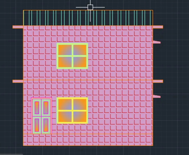
ELEVATION VIEW
2) STRUCTURAL DRAWING
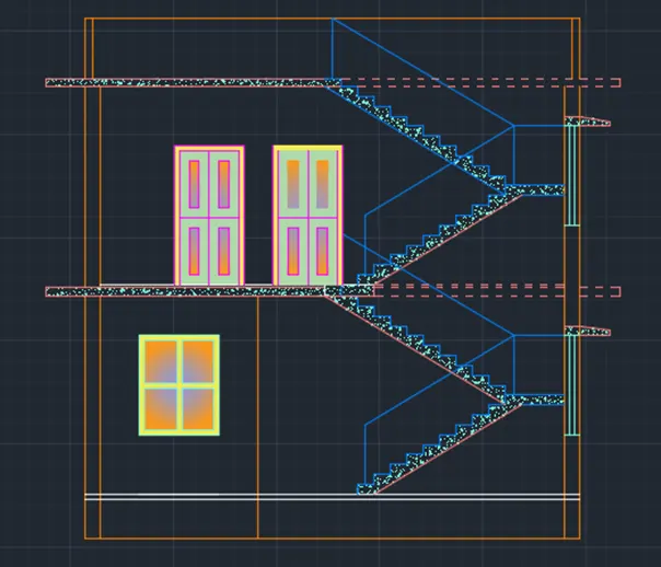
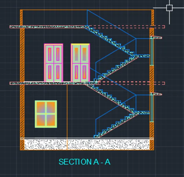
SECTION VIEW
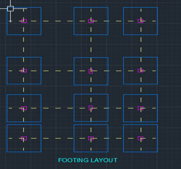
FOOTIG LAYOUT
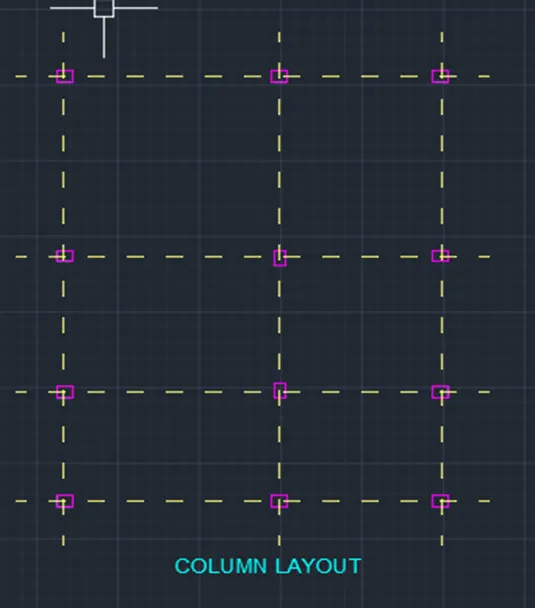
COLUMN LAYOUT
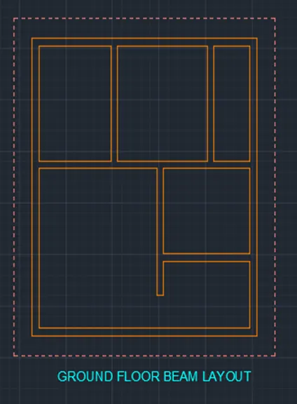
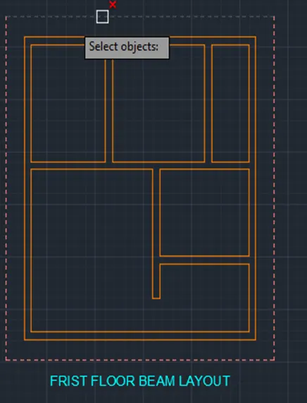
BEAM LAYOUT
INTRODUCTION :
The residential building to be drawn with plot dimensions are 60' x 20'.
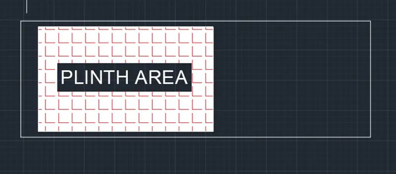
The plinth dimensions are chosen as 30' x 18'
The G+1 floor is designed as duplex house with stairs inside the home.
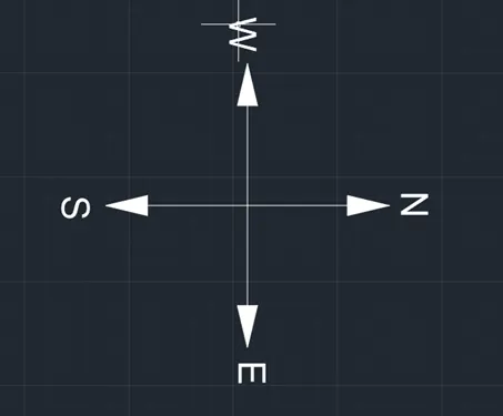
The plot is east facing.
The building is designed with following rooms
Ground floor great room
Kitchen (open)
In ground floor two bed rooms
Staircase to first floor
First floor great room
In first floor two bed rooms
Balcony
Staircase to roof
Building is designed with main door at the north east facing north and main gate at east north position. Initially layers are created for all the components of the house.
The dimensions of the components of house are as follows
WALLS
Thickness of main walls is taken as 9"
Internal wall thickness is taken as 4.5"
COLUMNS AND BEAMS
All the columns size are 9" x 12"
All the beams size are 9" x 9"
Rebar specifications
DOORS
Doors are three types are used
Main door ( d1 ) size is 4' x 7'
D2 door size is 3'6" x 7'
D3 door size is 3' x 6'
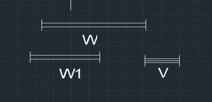
WINDOWS
Windows are two types are used
W windows size is 6' x 5'
W1 windows size is 4' x 5'
VENTILATORS
Ventilators are one types are used
V ventilator size is 2' x 2'
STAIRCASE
Inner staircase consist of 21 steps
Thread and raiser are taken as 10" and 6"
Hand rails are 2" in diameter and height of 3'
COMPOUND WALL
Height of compound wall is taken as 6'
Thickness of compound wall is similar to wall thickness is 9"
PROCEDURE :
Open AutoCAD
Change units as your required
Type un in command box and press enter
Change units type to decimal and precision to 0.00 and insertion scale to millimeters
Next type ‘D’ in command box and press enter
Change dimension style as based on units
Command used in this
Units command
Dimension style command
Line command
Trime command
Rec command
Dim command
Offset command
Circle command
Block command
Edit command
Insert command
Attribute command
Text command
In above drawing all the lines are drawn by using the line command in the below command section.
All the text in the above drawing are written by using the line command
Dim command is used to give all the dimensions to the drawing
Trim command is used to remove unwanted objects from the drawing.
Rec command is used to draw the tables
Offset the templates all the templates are created as blocks
All the blocks are saved by different names to different blocks.
The text inside the blocks are edited by using attributes.
Then insert tool and we can insert the created blocks in the drawing by using insert command.
Circle command is used to draw all the circles in above drawing.
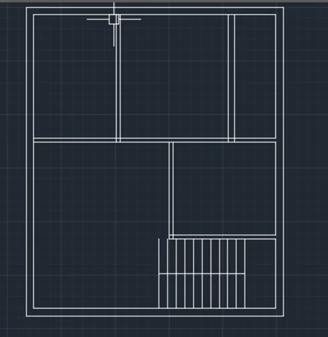
To set the drawing units of the sheet.
To drawn the horizontal and vertical lines by using the construction line command.
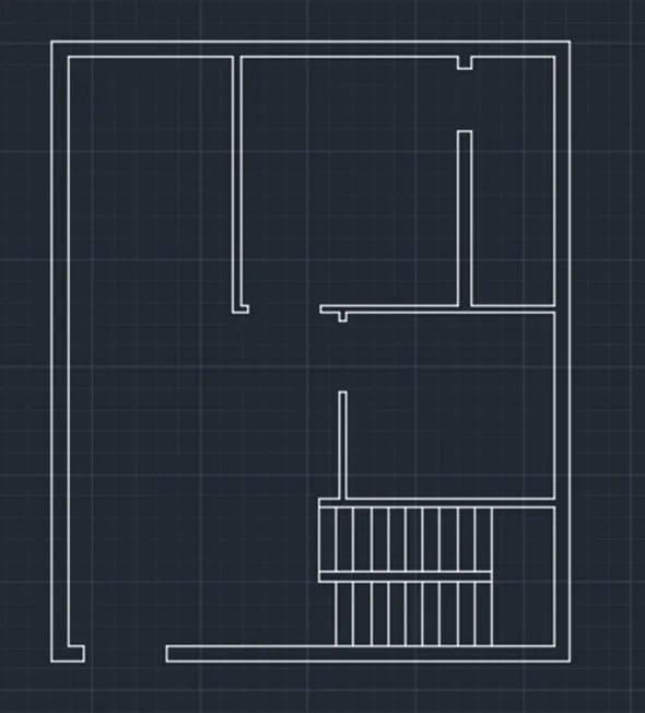
To create the corner by using the trim command.
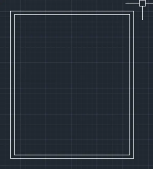
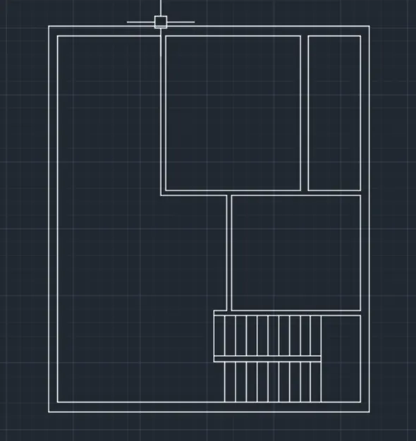
In order to create outer wall of 250mm thick by using the offset command.
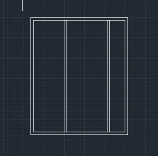
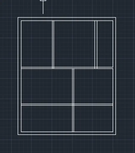
In order to create rooms as per required room sizes by using the offset command.
In order to create internal wall of 150mm thick by using the offset command.
In order to remove the extra lines by using the trim command.
Type hatch in command box and click on hatch command
In order to create the section line as your required section a - a.
To projection the line as per section line by using the construction line command.
To drawn the final section a - a by use of projection lines
The parapet wall, stairs and the overhead tank are drawn as per the dimensions by using required commands.
Type hatch in command box and click on hatch command
In order to create the section line as your required section a - a.
To projection the line as per section line by using the construction line command.
To drawn the final section a - a by use of projection lines
The parapet wall are drawn as per the dimensions by using required commands.
Type hatch in command box and click on hatch command

RESULT :
ARCHITECHTURAL DRAWING
1 PLOT DRAWING
2 GROUND FLOOR PLAN
3 FIRST FLOOR PLAN
4 ELEVATION VIEW
STRUCTURAL DRAWING
5 SECTION VIEW
6 FOOTING LAYOUT
7 COLUMN LAYOUT
8 BEAM LAYOUT