Project 1 _Creating an Architectural plan for the provided plot size and develop relevant basic structural drawings
Aim;
Design and Draft a layout of a residential building with the following details:
a. Plot Size: 60’x20’(18.3m x6m)
b. Orientation- Facing East
c. Develop the following: 1. Architectural Drawing (Floor Plan, Elevations, and Sections) 2. Structural Drawing (Column, Bean, Footing Plan)
Comments used;
- units
- limits
- line
- xline
- multiline
- layers
- matchproperties
- hatch
- block
- offset
- trim
- rectangle
- extension
INTRODUCTION
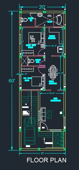
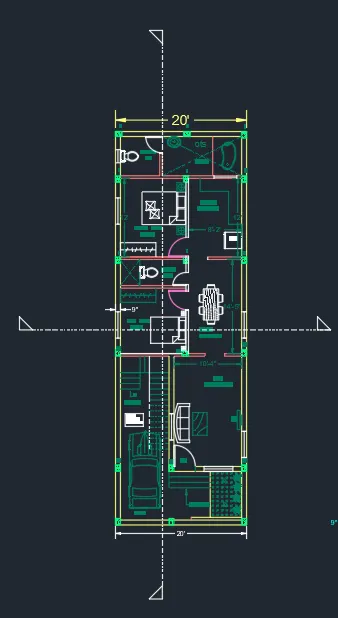
Drawing the residential building of gf in a plot size of 20'x60' . The building face on the east.
2 BHK plot consist of;
- Living room
- Bedroom 1
- Bedroom2
- Kitchen
- car parking
- attached bathroom
Dimensions
- dim of Outer wall-9"
- dim of inner wall - 4.5"
Doors & windows
- Main door-3.5'x7'
- inner doors- 2.5'x7'
- Mindows-4'x4'
PROCEDURE
Step-1;
First create the layers which are going to drawn.The layers as follows Outer line,inner line,staircase,dimensions,components,column,beam,footings,gridlines, ect
Step-2
In the commend pannel enter line or in the ribbon bar. First draw the line of the plot size as 60' vertically. Then the line of 20' horizondally. The plinth size is 20'x60' respectivly.
Step-3
In the commend pannel enter offset and offset it into 9" and to the inner wall offset it in4.5" wall.
The same off set is used for staircase.
Draw the staircase in a width of 3'. And the thread-10",Raiser-7'.
Step-4
In the commend pannel enter DC and insert the Housholds,Closets,gardenings,car,furnitures etc.
Step-5
In the commend pannel enter Block .draw the block to the certain standard areas.
drawn the column in the size of 12"x9". all the column size are same so create the block in the size of 12"x9".
And located it in the required places.
Step -6
In the commend pannel enter hatch . The Hatch is used in the column ,garden ,elivation etc
Step-7
In the commend pannel enter dim. draw the dimension in all the walls ,rooms required.
Strep-8
Creating the doors and windows.In the dimension of maindoor-3.3'x7' D2-3'x7'.
Windows dimension-4'x4'
Doors and windows are drawn in block.
Block can be edited in blockedit.
step-9
Finally mention the room dimensions using Text.
Result of floor plan
CREATING THE ELEVATION
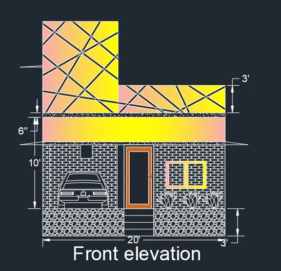
- For the front elevation make the base line .
- creating the construction lines with a base point of floor plan
- Create vertical extension line at all the wall edge points
- floor height of 10'6"
- In 7' lintel level in the thickness of 4.
- Using the Hatch option design the front elevation.
- finally mention the proper dimension to respective areas.
Front Elevation
CREATING SECTION;
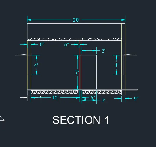
- Before creating the section draw the grid line in the center of the floor plan where we want to create the section portion.
- Draw the grid lines bith vertically and horizontally.
- Using ‘XLINE’ command draw the extension lines at the all the intersecting points of section line and walls
- Doors and windows are also drawn as per dimensions.
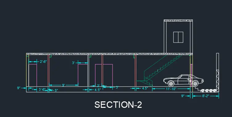
- And the section 2 is drawn on the another view.
- Staircase is drawn in the side view projection.
Section-1
SECTION-2
STRUCTURAL DRAWING
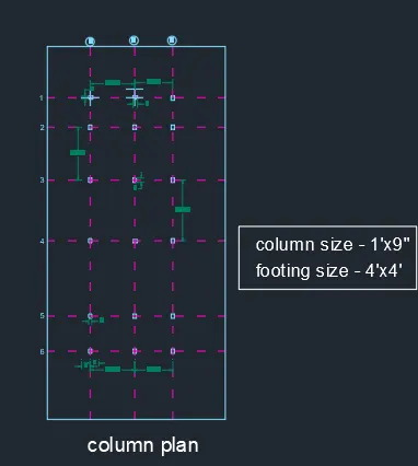
Colunm drawing;
step-1
- Draw all the walls of the plan view excluding doors and windows
Change the current layer to column layer
- using the rectangle command draw the column in the size of 12"x9".
- place all the columns in the corner of the walls and in the center wherever column requred.
- Columns are placed along the direction of wall in some cases
- Draw the columns at all necessary points
- Reinforcement in column consists of 6 bars of diameter 12mm bar.
- Stirrups of side 8mm dia bars with 150mm center to center spacing
- draw the grid lines with connecting the column.
- Name the vertical grid lines as A,B,C,D
- And name the horizondal lines as 1,2,3,4
- change the current layers into the column.
- Finally mention all the dimensions .center to center dimensions and column dimensions.
FOOTING PLAN
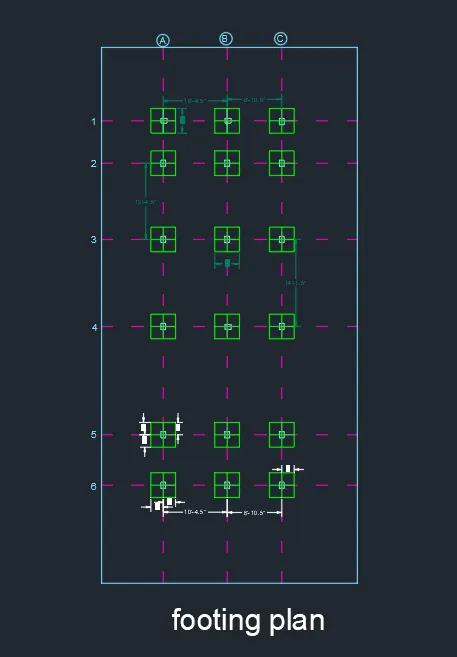
- Copy and draw the column layout again
- Change the current layer to Footing
- Draw the rectangle footing in the size of 4'x4'.
- follws as per the column layout
- Draw the center to center of footing layout and mention the dimensions.
FOOTING LAYOUT
PLINTH BEAM DIAGRAM;
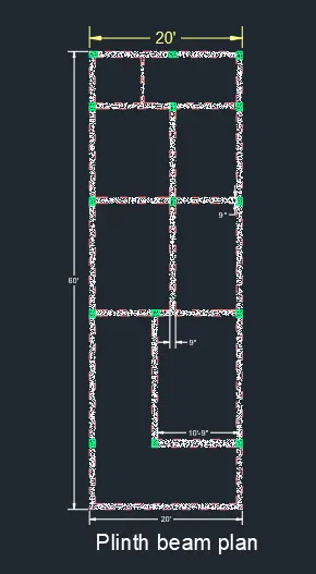
- Draw the column and wall layout of the floor plan
- Beams are drawn with dimension 9”X12”
- Using the hatch command show the beam.
Result:
East facing Residential floor design of plot drawing, plan view, center line drawing, column and beam layouts, elevation view and section views are drawn. The house consists of 2 bedrooms, 1 living rooms, puja room, kitchen and balcony. Layers are created in the first step and assigned accordingly. After drawing plan view one horizontal section and vertical section lines are drawn named as section 1-1 and section 2-2. Step by step procedure for all components is shown in respective steps.All the dimensions are in feet and inches.