Project 1 _Creating an Architectural plan for the provided plot size and develop relevant basic structural drawings
Design and Draft a layout of a residential building with the following details:
a. Plot Size: 60’x20’(18.3m x6m)
b. Orientation- Facing East
c. Develop the following: 1. Architectural Drawing (Floor Plan, Elevations, and Sections) 2. Structural Drawing (Column, Bean, Footing Plan)
Your Answers
Q. Design and Draft a layout of a residential building with the following details:
a. Plot Size: 60’x20’(18.3m x6m)
b. Orientation- Facing East
c. Develop the following: 1. Architectural Drawing (Floor Plan, Elevations, and Sections) 2. Structural Drawing (Column, Beam, Footing Plan)
AIM:-To create an own Architectural drawing consisting of Floor plan, Elevations and Sections for the plot size 60'x20' and also create the structural drawings for Column, Footing and Beam.
INTRODUCTION:-
The Architectural and Structural drawings are sketched up in AutoCAD using various tools / commands. The given details to draw the same in AutoCAD they are shown below:
- Plot Size - 60' x 20'
- Orientation - East Facing.
COMMANDS USED:-
- Layers
- Line
- Polyline
- XLine
- Dtext
- Dimlinear
- Dimcontinue
- Hatch
- Copy
- Fillet
- Trim
- Erase
- AutoDesk Design Centre
- Offset
- Block
PROCEDURE:-
- Open AutoCAD software
- Set the units to engineering and select ok
- Click z and enter for zoom
- Go to layer properties < create new layers < name the layers for reference < close.
- Architectural drawings:-
- Plan
- Elevation
- Section
- Structural drawings:
1.Column Layout
2.Footing Layout
3.Beam Layout
I. ARCHITECTURAL DRAWINGS:-
1. PLAN:-
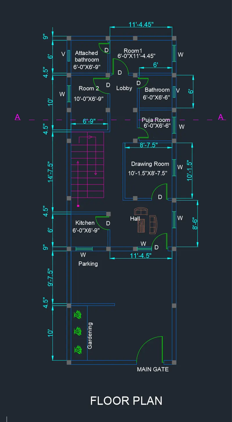
- Using the line Command, i draw the plot boundary of 60'x20'.
- The building's main entrance is facing the East direction.
- Using the commands line, offset, fillet and trim.
- I have used the offset of 9" for external wall
- For internal wall thickness is 4.5".
- I have provided the dimensions of rooms, toilets, kitchen, lobby, hall which is shown in drawing.
- It is planned as per VASTHU.
2. SECTION-AA:
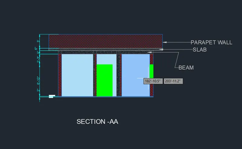
- Command used- Line, Polyline, Offset, Fillet, trim and layers for making the sectional view.
- Created block for window, and door.
- I have provided the beams and column as per required place.
- Introduced parapet wall.
- Using hatch command, I have differentiated the different part of drawing.
- Used Dtext command for text.
3. ELEVATION:-
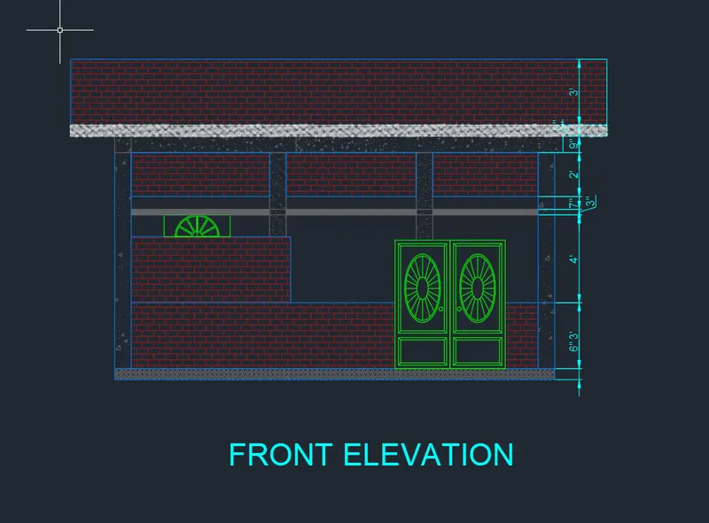
- Command used- Line, polyline, offset, fillet, trim and hatch.
- I have created the sectional view for the Elevation.
- I have provided the door and windows which is visible from frot elevation.
- I have given the hatch to the sub-structure and also for super-structure.
- Used Dtext for text commitments.
- I have used block for window and door insertion.
II. STRUCTURAL DRAWINGS:-
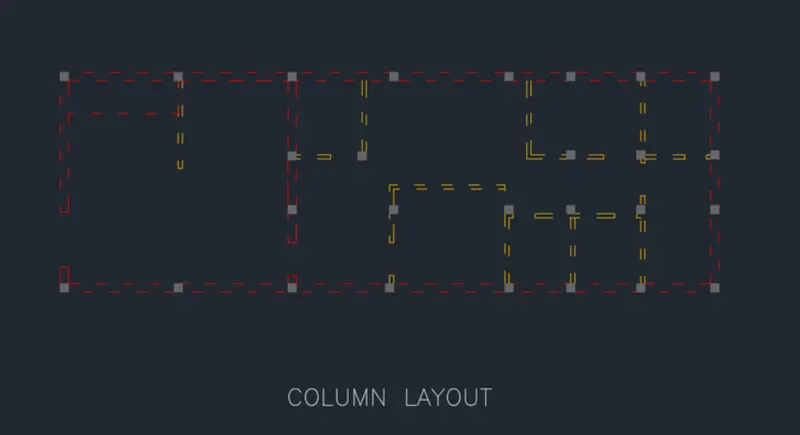
1. Column Layout:-
- I have turn off all the layers except the column layer and boundary layer in the layer properties.
- Used XLINE command in horizontal and vertical direction to connect all the columns.
- Trim the outer part of the Xline which is not in the boundary range of 60'x20'.
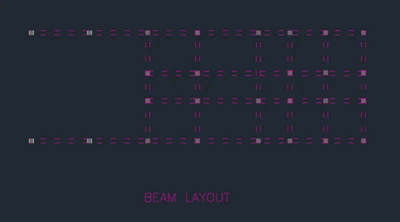
2. Beam Layout:- - I have turn off all the layers except the Beam layer and boundary layer in the layer properties.
- Used XLINE command in horizontal and vertical direction to connect all the columns and beams.
- Trim the outer part of the Xline which is not in the boundary range of 60'x20'.
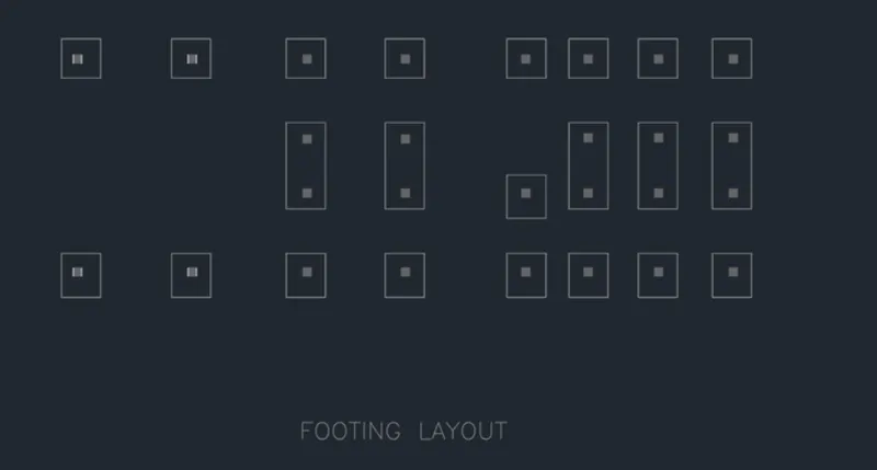
3. Footing Layout:- - I have turned off all the layers except the column layer and boundary layer in the layer properties.
- I have made rectangular isolated footing for all the columns.
- All footings are in placed in a structured manner.