Project 1 _Creating an Architectural plan for the provided plot size and develop relevant basic structural drawings
AIM:
Creating an Architectural plan for the provided plot size and develop relevant basic structural drawings
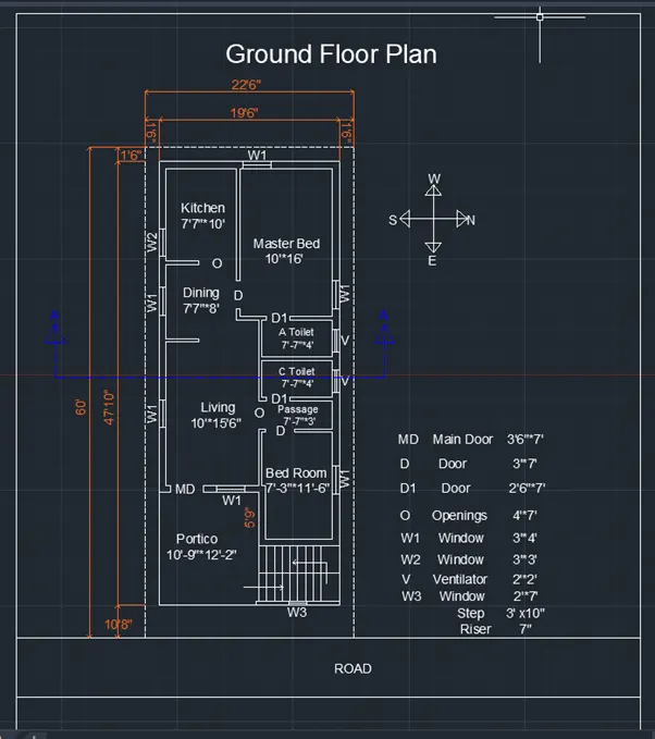
Design and Draft a layout of a residential building with the following details:
a. Plot Size: 60’x20’(18.3m x6m)
b. Orientation- Facing East
c. Develop the following: 1. Architectural Drawing (Floor Plan, Elevations, and Sections) 2. Structural Drawing (Column, Bean, Footing Plan)
Commands used:
- Line.
- Offset.
- Rectangle.
- Trim.
- Extend.
- Block.
- Block edit.
- Dimension.
- Layer.
- Hatch.
- Design centre.
Procedure:
- Go to AutoCAD and use unit commend to fix the units.
- Use Engineering and precision as 0’0” in units.
- The use line commends and draw a line in x axis and y axis.
- Then start sketching by using line commend.
- Use rectangle to draw a rectangle and line commend to draw a line.
- Then use offset to draw multiple lines at specific distance.
- Then use trim commend to erase excess lines.
- Then use circle commend to draw a circle.
- And line commend to draw lines at required places.
- Then provide m text to write the text. Change the size for better appearance.
- Use dimension commend to provide dimensions.
- Create separate layers for all the activities, like Walls, Doors, Windows, Text, Dimensions, etc.
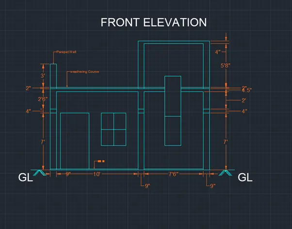
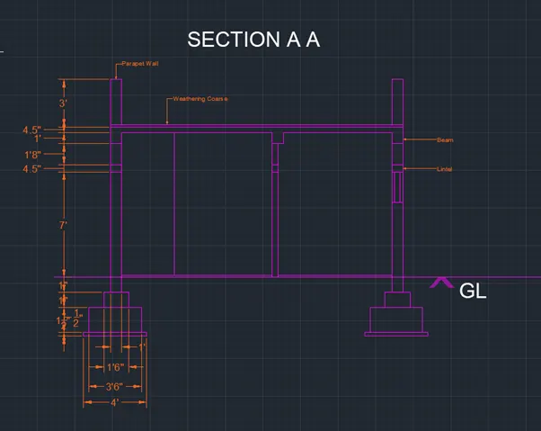
- Similarly draw elevation and section for the plan.
- Once Architectural plan, section and elevation completed.
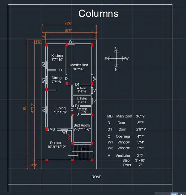
- Then start placing the columns and provide footing details and also the beam details.
- Draw all the columns, beams and footing in separate layout.
- Thus the plan section elevation and Column, footing and beams are designed for the residential building.
GROUND FLOOR PLAN:-
FRONT ELEVATION:-
SECTION AA:-
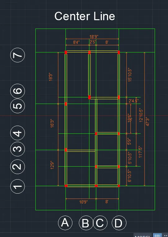
COLUMNS:-
CENTER LINE:-
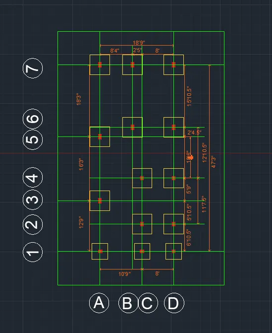
FOOTING
Result:-
Thus the Layout of residential building with Architectural plan, elevation section and structural columns, Beams and Footing details are designed by using Auto Cad Software.