Project 1 _Creating an Architectural plan for the provided plot size and develop relevant basic structural drawings
AIM - Design and Draft a layout of a residential building with the following details:
a. Plot Size: 60’x20’(18.3m x6m)
b. Orientation- Facing East
c. Develop the following: 1. Architectural Drawing (Floor Plan, Elevations, and Sections) 2. Structural Drawing (Column, Beam, Footing Plan)
Procedure
STEP 1: SITE LAYOUT
First the site plan is drawn using line command. Type L and press enter
Specify the first point:(0,0)
Specify the next point: 18300>0
Specify the next point: 6000>90
Specify the next point: 18300>180
Specify the next point: 6000>270
Type O or offset on the command line and press Enter.
Specify the value of offset distance:2000
Select the vertical line to offset and click inside it
Type O or offset on the command line and press Enter.
Specify the value of offset distance:1000
Select the Horizontal line to offset and click inside it
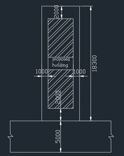
Two horizontal lines which are 500 mm apart are drawn to show the roads.
Using the hatch command hatch the proposed building area.
Hatch style ANSI32 was used here.
Using the dimensions command Dimlin the required dimensions was plotted and the following image is obtained.
SITE LAYOUT is drafted and the resultant image is as shown
STEP 2: GROUND FLOOR PLAN
1.External Walls
To create a Layer
In the Layer Properties Manager, click New Layer.
A layer name is added to the layer list.
Enter a new layer name as wall by typing over the highlighted layer name.
Select a suitable colour for that layer.
Using the construction line, offset, trim and fillet tool the external walls was drawn and a thickness of 230 mm was provided for these walls
2. Internal walls
The internal walls was also given the same layer as that of external walls.
The thickness of internal walls was taken as 150mm.
A small provision for sit out is also provided in the plan.
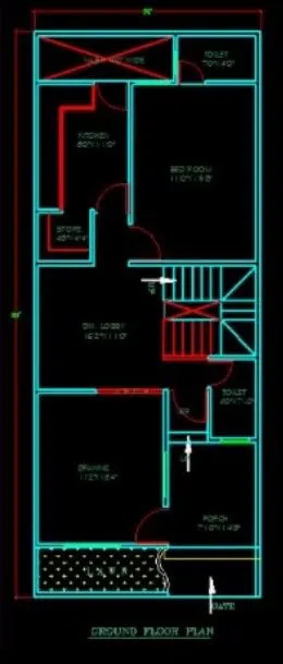
A hall of size 3540x3780mm was drawn and is followed by the rooms and size of rooms as follows.
Toilet-2940x1300mm
Bedroom-2940x3000mm
Dining area-3540x2350mm
Kitchen-3540x2200mm
A open kitchen dining layout is made for this plan and is separated from each other by a slab
The edges and corners after trimming or filleting the following image is obtained
3.Staircase and steps
A new layer is now created, named as staircase and a suitable colour is selected and this layer is made as the default.
The Dimension data of staircase is as follows:
Thread: 180mm
Riser: 160mm
Now using the line and offset tool staircase was drafted and the following image is obtained
The dotted lines ACAD_ISO02W100 indicating the upper part of staircase was also drawn by setting a global scale factor of 20.
The steps at the entrance portion is made next.
Thread:200
Riser:200
This was done with help of line and offset command
4.Doors
A new layer is now created, named as doors and windows and a suitable colour is selected and this layer is made as the default.
Two sizes of doors was made and the dimensions is as follows:
D1: 800x2000
D2:600x2000 mm
The doors was drawn with help of line, offset, trim and circle command.
5.Windows
The doors and windows layer was selected as default and the windows was plotted with the help of line, offset, trim command.
Different sized windows was made and the dimensions is as follows:
W1: 1500x1500 mm
W2:1200x1500 mm
W3:500x1500 mm
Along with the windows sunshade of 700mm width was also drafted using the dotted lines ACAD_ISO02W100
6.Ventilations
The doors and windows layer was selected as default and the single ventilation of size 600 mm was plotted with the help of line, offset, trim command.
7.Blocks
A new layer is now created, named as blocks and a suitable colour is selected and this layer is made as the default
Pre-existing block drawing of wash basin, dining table and closet blocks was placed at the correct places and the following image is obtained
8.Dimensions
A new layer is now created, named as dimensions and a suitable colour is selected and this layer is made as the default
Now using the Dimlin the dimensions was plotted and the following image is obtained
9.Texts
A new layer is now created, named as texts and a suitable colour is selected and this layer is made as the default.
Now using the MTEXT all the texts was made and the following image is obtained.
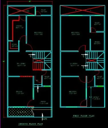
The ground floor plan was drafted in AutoCAD and the final image is as follows
STEPS 3: FIRST FLOOR PLANS
1.External walls
The wall layer which was created was made default layer.
Using the construction line, offset, trim and fillet tool the external walls was drawn and a thickness of 230 mm was provided for these walls
2.Internal walls
The internal walls was also given the same layer as that of external walls.
The thickness of internal walls was taken as 150mm.
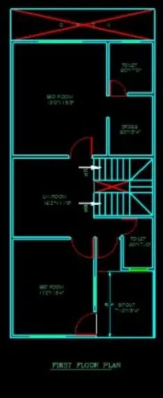
A hall of size 2490x22000mm was drawn and is followed by the rooms and size of rooms as follows.
Toilet-2490x1250mm
Bedroom-2490x2715mm
Toilet-2490x1250mm
Master bedroom-3540x2685mm
Balcony-3540x1390mm
The edges and corners after trimming or filleting the following image is obtained
3.Staircase
The staircase layer which was created earlier was made the default layer.
The Dimension data of staircase is as follows:
Thread: 180mm
Riser: 160mm
Now using the line and offset tool staircase was drafted and the following image is obtained
The dotted lines ACAD_ISO02W100 indicating the lower part of staircase was also drawn by setting a global scale factor of 20
4.Door
The doors and windows layer is selected and this layer is made as the default.
Two sizes of doors was made and the dimensions is as follows:
D1: 800x2000
D2:600x2000
D3:700x2000 mm
The doors was drawn with help of line, offset, trim and circle command.
5.Windows
The doors and windows layer was selected as default and the windows was plotted with the help of line, offset, trim command
The windows was plotted next and all the windows had the same dimensions:
W1: 1500x1500 mm
Along with the windows sunshade of 700mm width was also drafted using the dotted lines ACAD_ISO02W100
6.Ventilation
The doors and windows layer was selected as default and the ventilations of size 600 mm was plotted with the help of line, offset, trim command.
7.Blocks
The Blocks layer is selected and this layer is made as the default
Pre-existing block drawing of wash basin and closet was placed at the correct places and the following image is obtained
8.DIMENSIONS
The Dimensions layer is selected and this layer is made as the default
Now using the Dimlin the dimensions was plotted and the following image is obtained
9.Texts
The texts layer is selected and this layer is made as the default.
Now using the MTEXT all the texts was made and the following image is obtained.
The first floor plan was drafted in AutoCAD and the final image is as follows
STEP 4: ELEVATION
Type X L. in command box and press enter.
Click on ''ver" in command box.
Select the points required to take the projection for Elevation.
Draw a Horizontal line for Ground level which cuts all vertical line projections.
Now, type "Breakpoint" in the command box and break all the vertical projection lines from the point of intersect ion with horizontal line.
Type "E" for erase command and press enter.
Select all the vertical line below the horizontal line and press enter.
Mark this horizontal line as Natural Ground Level.
Type "O" for offset in command box and press enter.
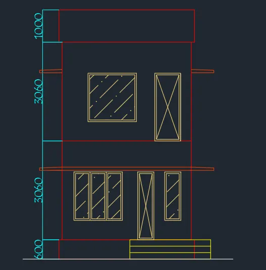
Specify offset distance as 600 and press enter.
Select the horizontal line drawn earlier and click on top.
Type "O" for offset in command box and press enter.
Specify offset distance as 3060 and press enter.
Select the last offset line and click on top.
Type "O" for offset in command box and press enter.
Specify offset distance as 3060 and press enter.
Select the last offset line and click on top.
Type "O" for offset in command box and press enter.
Specify offset distance as 1000 and press enter.
Select the last offset line and click on top.
Type 'TR" in command box for Trim command and trim the extra portions.
Change the current layer to “DOORS AND WINDOWS “layer.
Type "L" in the command box and press enter.
Draw the line connecting the door and window line projections at the ground-floor level.
The doors and windows are drawn with the help of line command.
The door size will be small as the door wall is not aligned vertically
Using the hatch command a suitable hatch pattern was given to the hatch the windows.
The sunshades was also drawn at this point of time.
Type 'TR" in command box for Trim command and trim the extra portions.
In the similar manner the first floor doors and windows was also drafted and hatched as in above steps.
The Staircase and steps layer was now made active.
The steps was projected as shown to draw the entrance steps
Type 'TR" in command box for Trim command and trim the extra portions
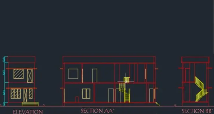
Using the DIMLIM command the dimensioning was done as required and the final elevation view of house is as shown.
STEP 5: SECTION DRAWING
The Ground floor and First floor plan are shown along with the section line AA' and BB,
Type X L in command box and press enter.
Click on ''ver" in command box.
Select the points required to take the projection for Section A-A.
Draw a Horizontal line for Ground level which cuts all vertical line projections.
Now, type "Breakpoint" in the command box and break all the vertical projection lines from the point of i intersection with horizontal li ne.
Type "E" for erase command and press enter.
Select all the vertical line below the horizontal line and press enter.
Take this horizontal line as N.G.L.
The plan dimension height is taken as follows
Plinth level 600mm
Floor thickness 125 mm
Room height 2935mm
Floor thickness 125 mm
Room height 2935mm
Parapet 1000mm
All the wall projections was projected as shown.
Type 'TR" in command box for Trim command and trim the extra portions.
Change the current layer to Door and window layer.
Type "L" in the command box and press enter.
Draw lines connecting the windows and the door positions in both ground and first floors.
From the projections we will easily get the dimension of windows and doors and was drafted
All the doors and windows projections was projected as shown.
Type 'TR" in command box for Trim command and trim the extra portions.
Change the current layer to Staircase and steps layer.
Type "L" in the command box and press enter.
Draw lines connecting the staircase and entrance steps positions in both ground and first floors.
From the projections we will easily get the dimension of steps and was drafted.
Thread of staircase-180mm
Riser of staircase-160mm
All the staircase and stairs projections was projected and drawn as shown and SECTION AA' is completed
Type 'TR" in command box for Trim command and trim the extra portions.
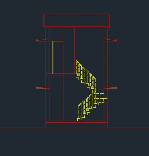
SECTION BB’
Type "XL'' in command box and press enter.
Click on "Hor" in command box.
Select the points required to take the projection for Section B-B.
Draw a Vertical line which cuts all horizontal line projections.
Now, type "'Breakpoint" in the command box and break all the vertical projection lines from the point of intersection with horizontal line.
Type "E" for erase command and press enter.
Using the projection all the wall parts was completed first
Draw the staircase with the taking the riser as 160mm and treads as 180mm.
Type 'TR" in command box for Trim command and trim the extra portions.
The section BB' is now complete
All the architectural drawing is now complete.
The Ground Floor Plan, First Floor Plan, Elevation, Section AA’ and Section BB’ is as shown as above
STEP 6: COLUMN LAYOUT
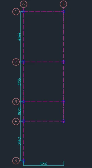
Turn off All the Layers except columns and center line.
Use the copy command and Select all the columns from plan view drawing and move them to a different position.
Select the layer "center line".
Type "L" for the line command and press enter.
Draw the center line through each column from their center point.
Extend the center lies a little from each column as shown below.
Type "c" in the command box and press enter.
Draw a small circle with respect to the drawing and press enter.
Copy the circle to extension point of center line and fill the text in-between the circle by typing "DT" command in the command box.
Turn all ayers on and select the dimension layer and give dimension to the drawing.
Give title to the drawing by using DT command.
Give names to each column in that layout
The Column layout is now completed and is as shown
STEP 7: BEAM LAYOUT
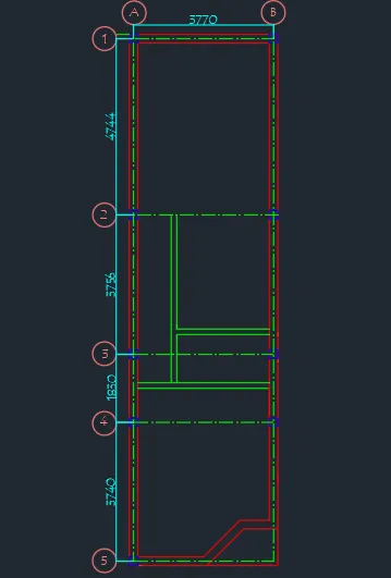
BEAM LAYOUT FOR GROUND FLOOR
Turn off All the Layers except columns,beam,centerline and walls.
Use the copy command and Select all the columns from ground floor plan view drawing and move them to a different postion.
join all the columns with line command for representing the beam.
Select the layer "Beam" and specify all the column joining lines in the beam layer.
Select the layer "center line".
Type "L" for the line command and press enter.
Draw the center line through each column from their center point.
The primary beams which connect from column to column is now completed.
Secondary beams are beams which connects from the primary beam.
All the internal walls are connected to the primary beams.
Extend the center lines a little from each column as shown below.
Type "c" in the command box and press enter.
Draw a small circle with respect to the drawing and press enter.
Copy the circle to extension point of center line and fill the text in between the circle by typing"DT" command in the command box.
Turn alll ayers on and select the dimension layer and give dimension to the drawing.
Give title to the drawing by using"DT" command.
Give names to each beam in the layout.
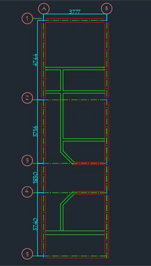
BEAM LAYOUT FOR FIRST FLOOR
Turn off All the Layers except columns,beam,centerline and walls.
Use the copy command and Select all the columns from ground floor plan view drawing and move them to a different postion.
join all the columns with line command for representing the beam.
Select the layer "Beam" and specify all the column joining lines in the beam layer.
Select the layer "center line".
Type "L" for the line command and press enter.
Draw the center line through each column from their center point.
The primary beams which connect from column to column is now completed.
Secondary beams are beams which connects from the primary beam.
All the internal walls are connected to the primary beams.
Extend the center lines a little from each column as shown below.
Type "c" in the command box and press enter.
Draw a small circle with respect to the drawing and press enter.
Copy the circle to extension point of center line and fill the text in between the circle by typing"DT" command in the command box.
Turn alll ayers on and select the dimension layer and give dimension to the drawing.
Give title to the drawing by using"DT" command.
Give names to each beam in the layout
STEP 8: FOOTING LAYOUT
Use the copy command and Select column layout drawing and move it to some other location.
Select the layer "center line".
Type "L" for the line command and press enter.
Draw the center line through each column from their center point.
Extend the center lines a little from each column as shown below.
The size of the Isolating footing is taken as 1000x1000.
Type "c" in the command box and press enter.
Draw a small circle with respect to the drawing and press enter.
Copy the circle to extension point of center line and fill the text in between the circle by typing "DT" command in the command box.
Turn all layers on and select the dimension layer and give dimension to the drawing.
Give title to the drawing by using "DT" command.
Give names to each column in the layout
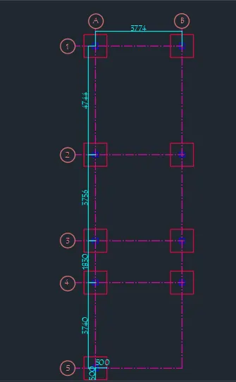
Result - All the architectural drawing and structural drawing of the house in the plot 18300x6000 mm facing east is drafted and The Ground Floor Plan, First Floor Plan, Elevation, Section AA’ and Section BB’ is completed And The Structural Drawing COLUMN LAYOUT, BEAM LAYOUT AND FOOTING LAYOUT Is Now Completed.