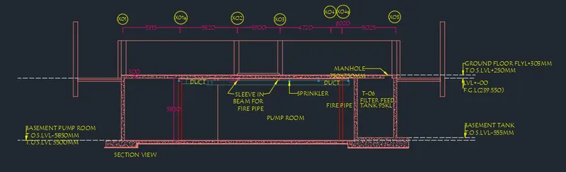
Creating Kitchen layout, Hatching of Architectural elements and sectional view of an Industrial Building in AutoCad
AIM - Creating Kitchen layout, Hatching of Architectural elements and sectional view of an Industrial Building in AutoCad
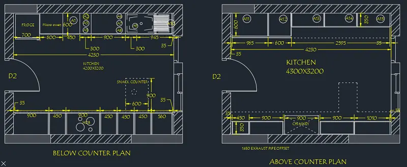
Challenge 1 - Create the layouts of the Kitchen and provide hatches pattern as shown. Also, use blocks wherever required. Provide appropriate dimensions in the plan. Assume the size of doors, appliances and others as per the standards.
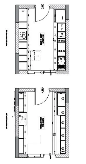
Procedure -
Type UN and press enter
Under Drawing Units, select decimal
Now the lower limit is set to 0,0 and upper limit to 15000, 15000
Type Z enter to zoom and A enter to all
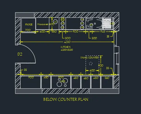
First of all the below counter plan was drawn. For that a rectangle of size 4734x3688 was created and an offset of 250 was taken to the inside of rectangle. Then a line was drawn from both sides at a distance of 600 mm.
A rectangle of width 35 is drawn at 3 corners in order to separate between the kitchen walls and the counter. Now using the line command all the cabinets was drawn as per the plan given.
The circle command ws used to plot the hob line,arc and circle command was used to zinc at top corner and the snack counter was drawn using the dotted lines.
Door opening and doors was placed next and the components inside the walls was drawn as shown. This was done using line, offset and circle command
Now hatching was done with required solid and pattern styles and was set to a transparency to 75.
Now all the dimensions was plotted and all the text was plotted as required and the final image of below counter plan is as follows
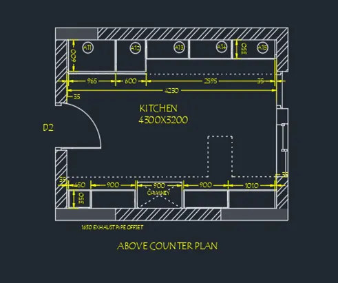
The above counter plan was next plotted. The outline of this plan is way too similar to below counter plan only the difference is the size of counters. After drawing the counters, dimensioning and text placing was done and the final image of above kitchen plan is as follows
The above and below counter plan was plotted and the resultant image is as follows.
Challenge 2 - Create the elevation of the plan created in the Challenges 7 and apply proper hatch in the walls, doors, windows, and other architectural elements. Refer to the dimensions in Plans and sections in Challenges 7. Refer to the elevation that needed to be created.
Procedure -
Under Drawing Units, select decimal
Now the lower limit is set to 0,0 and upper limit to 15000, 15000
Type Z enter to zoom and A enter to all
Go to the Draw panel on the Home tab. Find the hatch icon in the bottom right corner.
In "Hatch creation” tab. Go to its Properties panel and choose the Hatch type that you would like to insert. Here Solid and Pattern type was used.
In hatch settings "create separate hatches" options was selected, so that each entity will remain as an individual if any correction was to be made, else it would have to be done from first.
Pick points options was was to hatch the area. The “Pick Points” will determine a boundary around the specified point.
After filling the area, hit “Enter” to apply the hatch.
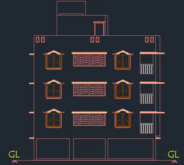
Hatching of walls
Go to the Draw panel on the Home tab. Find the hatch icon in the bottom right corner.
In "Hatch creation” tab. Go to its Properties panel and choose the Hatch type that you would like to insert. Here gradient of one type was used here also.
In hatch settings "create separate hatches" options was selected, so that each entity will remain as an individual if any correction was to be made, else it would have to be done from first.
Pick points options was was to hatch the area. The “Pick Points” will determine a boundary around the specified point.
After filling the area, hit “Enter” to apply the hatch.
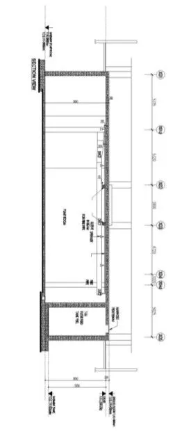
Challenge 3 - Create the section view of an industrial building as shown in Figure. Provide appropriate hatches and dimensions wherever required. Also, provide annotations to the drawing.
Procedure -
To create a Layer
In the Layer Properties Manager, click New Layer.
A layer name is added to the layer list.
Enter a new layer name as Walls by typing over the highlighted layer name.
Select a suitable colour for that layer.
Now using the line,rectangle, offset, trim,fillet commands all the wall portions was completed.
Hatching of walls
Go to the Draw panel on the Home tab. Find the hatch icon in the bottom right corner.
In "Hatch creation” tab. Go to its Properties panel and choose the Hatch type that you would like to insert. Here pattern type was used for hatching. 8
In hatch settings "create separate hatches" options was selected, so that each entity will remain as an individual if any correction was to be made, else it would have to be done from first.
Pick points options was was to hatch the area. The “Pick Points” will determine a boundary around the specified point.
After filling the area, hit “Enter” to apply the hatch.
A new layer is now created, named as texts and a suitable colour is selected and this layer is made as the default.
Now using the MTEXT all the texts was made and the following image is obtained.
A new layer is now created, named as Dimensions and a suitable colour is selected and this layer is made as the default.
Now using the Dimlin the dimensions was plotted and the following image is obtained