Project 1 _Creating an Architectural plan for the provided plot size and develop relevant basic structural drawings
Aim:
To Design and draft a layout of a residential buildings of size (60’ x 20’) and develop Architectural Drawings , Structural Drawings.
Procedure:
- Open the Autocad Software and enter the file name and save the file
- Set the limits and units as per the requirement
- Draw the Direction indication for the project site
1. PLAN:
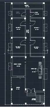
1. Using the line command draw the Boundary line 60’ x 20’
2. By using the offset command give 9” offset to the walls from the boundary layer
3. Then draw the rooms required as per requirement and Vasthu
Main Door – (EAST)
Stairs – (NORTH- EAST)
Dinning / Kitchen – (SOUTH – EAST)
Living Room - (NORTH- EAST)
Bed Room 1 – (NORTH)
Bed Room 2 – (SOUTH)
Bed Room 3 – (NORTH)
Bed Room 4 – (SOUTH)
Toilet 1 – (NORTH – WEST)
Toilet 2 – (SOUTH – WEST)
Balcony – (WEST)
4.Give 4.5” offset to the internal walls
5.Then use the TRIM command to trim the extended lines
6.The Door sizes are drawn as per the given dimensions below
MD – 4’ x 7’
O – 3’ x 7’
D1 – 2’6” x 7’
D2 – 2’ x 7’
7. The windows and ventilators are drawn as per the given dimensions below
W1 – 4’ x 4’
W2 – 4’ x 4’
V1 – 2’ x 2’
8. Give the openings to doors, windows and for ventilators
9. After drawing the windows draw the sunshade by creating the new layer
10. Using D Text command the names for each rooms and dimensions text are entered for windows, ventilators and doors.
11. Then draw the stairs by giving 6” – Riser and 9” – Footer , Landing size is 6’ x 3’
12. Draw the rectangle for the column of size 9” x 1’ and By using HATCH – Command (H – Enter ) Hatch the column
13. Dimension lines are drawn as per Using the DIMLINEAR Command – (DIMLIN – Enter)
14. Create the layers by using layer command LA – Enter for Texts, Dimension line, Doors, Windows, Columns
15. Then cut the Plan into two Sections as (SECTION -AA and SECTION – BB)
2. SECTION – AA:
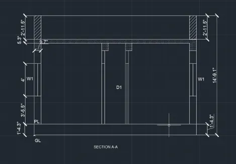
1. Using the command like Line, Polyline, offset, fillet and Trim commands the section AA is drawn
2. Then the Section is drawn as per the Elevation view by giving Windows, columns, walls, room spaces and stairs as per the plan
3. Draw the Lintel beams over the 7’ height from the FL (FLOOR LEVEL) over windows and doors
4. Then draw the Slab of height 10’ feet from the FL (FLOOR LEVEL) of 6” Thickness
5. Draw the parapet wall of height 3’ From the Slab top level
6. By using HATCH Command (H – Enter) Hatch the every Columns , brick wall and Sand filling hatching works
7. By Using DIMLINEAR Command (DIMLIN – Enter) draw the dimension lines to the Sections drawn.
2. SECTION – BB:
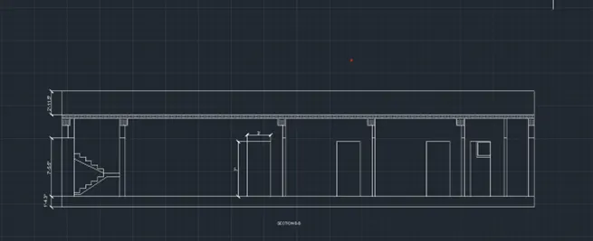
1. Using the command like Line, Polyline, offset, fillet and Trim commands the section- BB is drawn
2. Provide Windows, Doors , columns, walls, room spaces and stairs as per the plan
3. Use TEXT command (DTEXT - Enter) and enter the Room names and sizes in text
4. By using HATCH Command (H – Enter) Hatch the every Columns , brick wall and Sand filling hatching works
5. By Using DIMLINEAR Command (DIMLIN – Enter) draw the dimension lines to the Sections drawn
Provide the parapet wall of height 3’ From the Slab top level
ELEVATION:
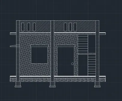
1. Using the command like Line, Polyline, offset, fillet and Trim commands the sectional view for elevation is drawn
2. Draw the Sub Structure of the building by drawing the plinth beams and grade beams as per the plan
3. Then draw the doors , windows, balcony , Chajja, as per the plan
4. By using Command HATCH – .(H - Enter) option , Hatch the Foundations, Footings, Columns, Basement, Main walls and parapet walls
5. Draw the staircase as per the per in the elevation view
6. Then draw the parapet walls at the 3’ height from the roof slab.
STRUCTURAL DRAWINGS:
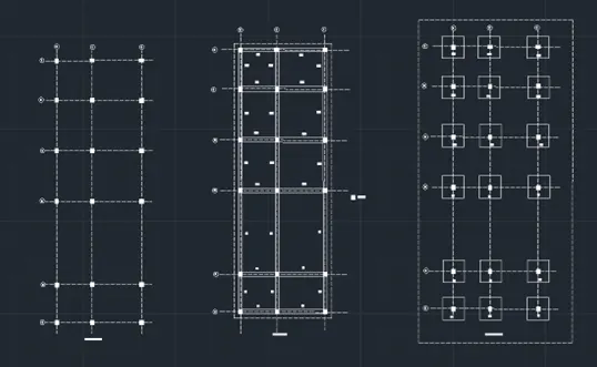
COLUMN LAYOUT:
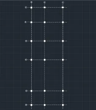
1. Draw the Boundary line as per the plan in the dotted lines layer and then create columns.
2. Turn Off the Wall Layer and other layers except the column layer to display the column.
3. Create a rectangle of size 12” x 9” for the columns to be drawn.
4. Using the HATCH Command hatch all the columns
5. Keep the center to center distance and place the Columns
6. By using DIMLINEAR command the dimensions lines are drawn in the column layout
7. Then draw the horizontal and vertical lines to center of the columns and denote Alphabet for Horizontal and Numeric for Vertical directions
8. Then mention the name for the each column as C1, C2, C3,…. Etc by using MTEXT command
9. Then Trim the extended lines using the TRIM Command.
10. Using DIMSTYLE Command the change the Dimension style as per the requirement
BEAM LAYOUT:
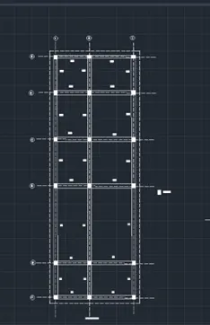
1. Draw the Boundary line as per the plan in the dotted lines layer and then create columns.
2. Make the dimensions, Texts, Windows and Doors Layer are Turned Off and other layers except the column layer and beam layer to display the columns and beams.
3. Create a rectangle of size 12” x 9” for the columns to be drawn.
4. Using the HATCH Command hatch all the columns
5. Then connect all the columns by drawings the beams and name them
6. By using DIMLINEAR command the dimensions lines are drawn in the beam layout
7. Then mention the name for the each column as B1, B2, B3,…. Etc by using MTEXT command
8. Then draw the horizontal and vertical lines to center of the columns and denote Alphabet for Horizontal and Numeric for Vertical directions
9. Then Trim the extended lines using the TRIM Command.
10. Using DIMSTYLE Command change the Dimension style as per the requirement
FOOTING LAYOUT:
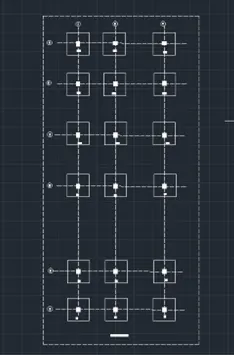
1. Draw the Boundary line as per the plan in the dotted lines layer and then create columns and footings.
2. Turn Off the Wall Layer and other layers except the column layer and footing layer to display the column and footing.
3. Create a rectangle of size 12” x 9” for the columns to be drawn.
4. Then create another Rectangle for footing of size 4’ x 4’
5. Using the HATCH Command hatch all the columns
6. Keep the center to center distance and place the Columns and footings
7. By using DIMLINEAR command the dimensions lines are drawn in the Footing layout
8. Then draw the horizontal and vertical lines to center of the columns and denote Alphabet for Horizontal and Numeric for Vertical directions
9. Then mention the name for the each Footing as F1, F2, F3,…. Etc by using MTEXT command
10. Then Trim the extended lines using the TRIM Command.
11. Using DIMSTYLE Command the change the Dimension style as per the requirement
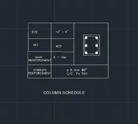
COLUMN REINFORCEMENT SCHEDULE:
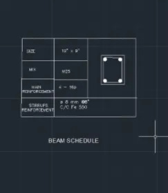
BEAM REINFORCEMENT SCHEDULE:
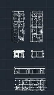
PLAN , SECTION , ELEVATION are drawn below:
STRUCTURAL DRAWINGS:
RESULT:
Hence the Architectural drawings and structural drawings are drawn.