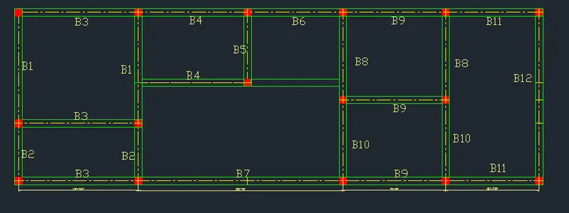
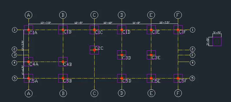
Project 1 _Creating an Architectural plan for the provided plot size and develop relevant basic structural drawings
|
Project : - Creating an Architectural plan for the provided plot size and develop relevant basic structural drawings |
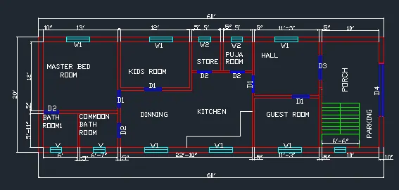
- Aim :- To draw the Residential Building in the plot size of 60’ X 20’ ( 18.3m X 6m ) facing East direction with the following drawings :
-
Introduction:
The architectural drawing is a technical drawing that used to develop a design idea into a coherent proposal, to communicate ideas and concepts to convience clients of the merits of a design, to assist building contractor to construct based on the design intent. architectural drawings are made acoording to a set of conventions, which includes particular views (Floor, plan, section etc), sheet size, units of the measurment, and scales, annotation and cross referring.
- Floor Plan: A floor plan is a fundamental architectural drawing, a view from the above showing the arrangement of the spaces in a building in the same way as a map. but showing the arrangements of a at particular level of the building. Technically it is the horizontal section cut through the building, showing the walls, windows, and door openings.and other feature at that level. the plan view includes anything that could be seen below the levels, floors, stair and sometimes furniture.
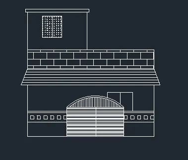
- Elevation: An elevation is a view of building seen from one side, a flat representation of of one facade. this is the most common view used to described the external appearance of the building. Buildings are simple rectangular shape in the plan, so typically the elevation may show the all parts of the buildings that are seen from the particular direction.
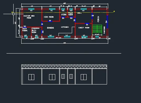
- Cross Section: A cross section is also simply called as sections, represents a vertical plane cut through the object in the same way as floor plan is the horizontal section viewed from the top. in the section view everything is cut by a section plane is shown in the bold line often with the solid fikl to show the object thatb are cut through, and anything seen beyond that line shwn in thin line. sections are used to described the relation between different levels of the buildings.
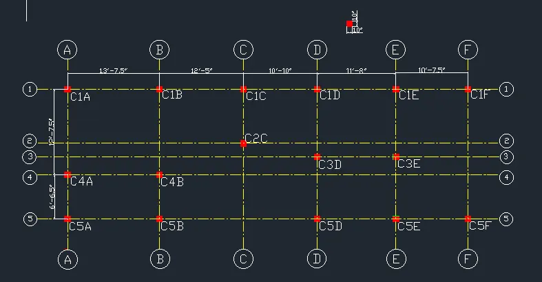
A structural drawing is a type of engineering drawing is a plan or set of plans and details for how the buildings or other structures are built. structural drawings are generally prepared by registred profesional engineers. and based on the information provided by the architectural drawings are primarly concern with the load carrying the members of a structure. they outline size and types of the materials to be used as well as the general demands for the connections. they do not address the architectural details like surface finishes, partition walls etc. the structural drawings commuicate the design of the building structure to the building authority for the review. structural drawing also included with the proposed building contract documents, which guide contractors in detailing, fabricating, and installing the parts of the structures. the structural drawings are used to progress the the architect concept by specifying the shape and position of the all parts of the structure on site. Structural drawings are used to for the preparation of the reinforcemets details. structural drawings are typically includes setting out dimensions for the concrete structures on the site, plans, sections and elevations showing the layout, dimensions and levels of the all concrete members within the structures, location of the all holes, chases, pockets, fixing and other items affecting the concreting the work. notes onn the specification, finishes and all cross references affecting the construction.
Commands used for drawings:
- Unit command
- limit command
- Xline
- Line command
- Offset
- Copy
- Move
- Mirror
- Trim
- Block
- Insert
- Dim linear
- Dimcontinuous
- Dtext
- Bedit
- layer
- Rectangle command
- The dimensions:
-
- For external wall – 10"
- For internal wall – 5"
- For Staircase : - Treads : 8",Riser-6.2"
For Windows:
- W1-4'x4'
- w2-2'5"x3'
- V – 2'5"x2'
For Doors:
The assumed dimensions :- D1 – 3'x6'5"
- D2 – 2'5"x6'5"
- D3 – 4'x6'5"
- D4- 9'x6
-
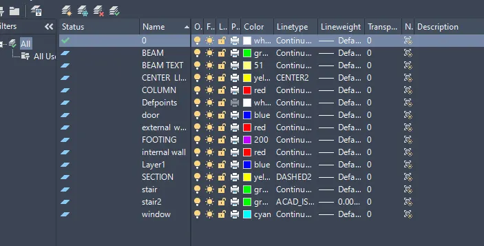
- Click on layer properties
- Click on new layer
- Give the layer name > Wall
- Turn the layer ON
- Set Unlock
- Slect layer colour > Red
- Similarly, use this above process to provides the layer
- The layers which are assigned are shown in below fig
- DRAWINGS