Project 1 _Creating an Architectural plan for the provided plot size and develop relevant basic structural drawings
AIM:
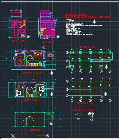
To draw residential building of dimensions 60'x20' with following drawings.
- Plot drawing
- Ground floor plan
- First floor plan
- Terrace
- Elevation
- Footing layout
- Beam layout
INTRODUCTION:
The residential building to be drawn with plot dimensions 60'x20'. the G+1 Floor is designed as duplexhouse with staircase inside the house. The plot is EAST facing. The building is designed with following rooms.
- Ground floor plan
- Living room
- Kitchen
- Puja room
- Staircase firstfloor
- Master Bed room
- Bed room-2
- Toilet

- Building is designed with main door at the (east-south) facing north and main gate at EAST-SOUTH Position. intially layers are created for all the components of the house.
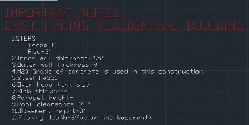
- The dimensions of mainwall thickness is taken as 9".
- The internal wall is taken as 4".
PROCEDURE:
- Open AUTOCAD.
- In stat-up setting from scarch select imperial (feet & inches).
- Open grid and snap settings.
- Type 'UN' in command box & press enter.
- Change units type to decimel and precision to (0'-0").
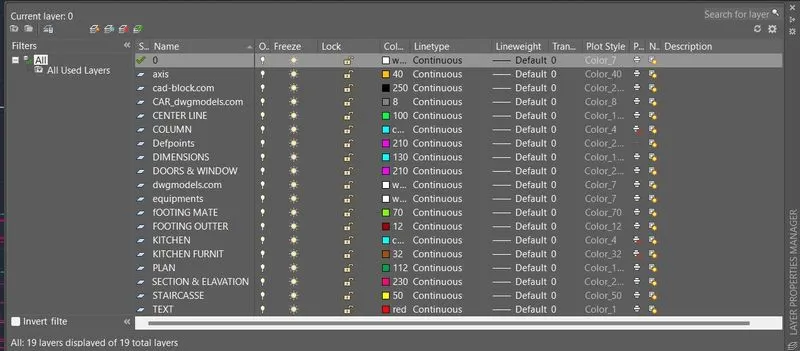
STEP-1 CREATING LAYERS:
Open layers properties and create and create new layers by clicking on new layer or right click on any layer and select new layer to create new layers.
Layers are created as follows.
COMMENDS USED:
- Line
- Offset
- Rectangle
- Trim
- Extend
- Block
- Block edit
- Dimension
- Layer
- Hatch
- Design centre.
PROCEDURE:
- First set the units in decimel meters and Set the limits and zoom all (Command -Z-a).Set the dimension to decimal units and set the precision.Architectural drawing of residential building.
- Drawing wallOffset 9" from the boundary after the setback is taken for the wall thickness.
- As the orientation is given as East, main door should face East.
- As per Vaastu Shastra, North-East is favourable for living room and the entrance should faceEast.
- Offset 9" horizontally from dinning wall and 9" vertically.The size of kitchen is 12'7"X7'9" Trim 3' for the door opening. According to Vaastu Shastra the ideal position for kitchen is EAST-WEST ,with cooking place facing East.
- Place the doors and windows in the respective places.
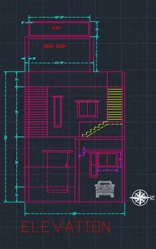
- Elevation part the Projecting lines to draw the elevation.Project the wall lines to the top.
- Trim off the extension lines and make shutters and panels for doors and windows.For architectural purpose, create some hatches.
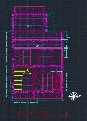
- Project the lines from the elevation for the height and from the section line of plan for the horizontal members. Drawing windows, doors and stairs in section.
- Using hatch hatch the walls with the bricks hatch and foundation with the concrete hatch.
- Project the lines from the elevation for the height and from the section line of plan for the horizontal members.
- Drawing windows, doors and stairs in section.Draw the window and door which we see after cutting the section line.
- Using hatch hatch the walls with the bricks hatch and foundation with the concrete hatch.
- Place the windows and foundations in the respective layers and give colours.
- The same procedure as follows GROUNDFLOOR,FIRSTFLOOR,AND TERRASE Also.
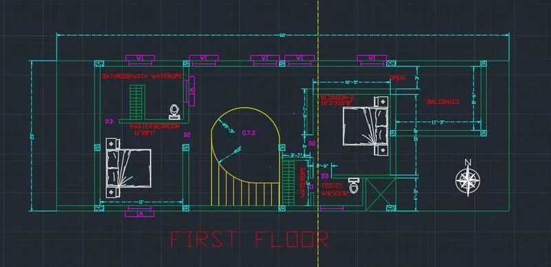
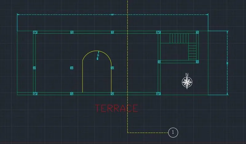
STRUCTURAL DRAWINGS:
Column layout:
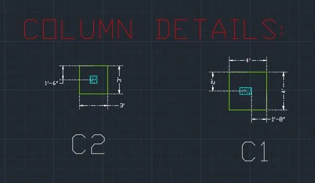
- Column of size C1-4'X4',C2-3'X3' is considered.Columns are placed in all corners of the wall and intersection of walls wherever required.
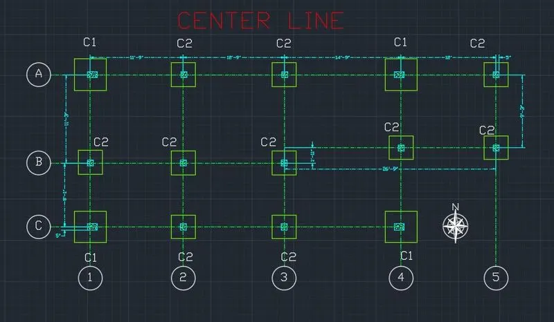
- Now draw the centre line for column from the annotate tab -centre line and mark the grid line as 1,2,3,4,5 in the X direction and A, B, C in the Y direction.
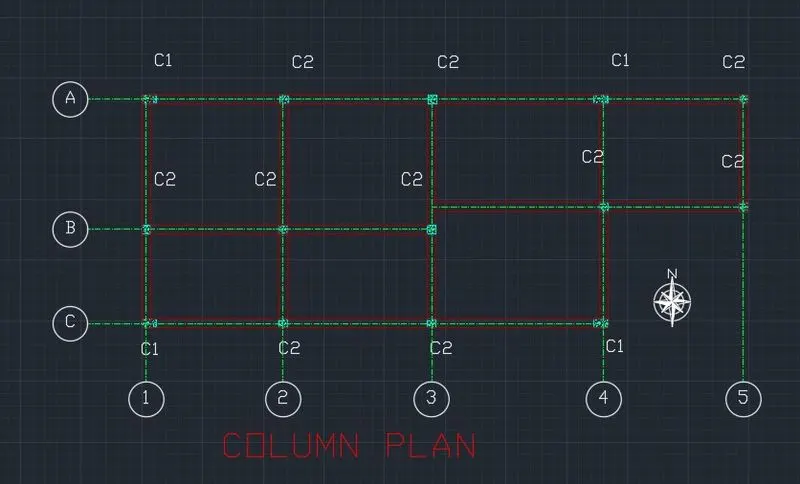
CENTER LINE DRAWING:
- Change the current layer to center line.
- Draw the lines connecting centres of all columns in line.
- Both horizontal and vertical center lines are drawn.
- Give codes with alphabets for vertical center lines.
- Give code with number for horizontal center lines.
- The distance from one center line to another is to be shown.
HATCHING:
- The hatching is done for all components of plan & elevation.
- Elevation pattens are chosen and applied with this respective attributes.
- Hatch pattens used for respective properties.
- all walls in top view, side view, front view are hatched.
- all columns are hatched.
- all beam,loft,slab are hatched.
RESULT:
Residential G+1 Floor design consists of drawing ,plan view, column lauouts, elevation view, and section views are drawn. The house consists of 2 bed rooms, living room, puja room, kitchen & bolcony. Layers are created inthe firststep designed accordingly. After drawing plan view one horizontal section lines are drawn named section1-1. Required components and furniture to the house are added using design center command and some other files are added from the CAD BLOCKS from browsing. Step by step procedure for all components is shown in respective steps. At the end of each step. Result of that step is shown. The final result consists of all drawings of the residential house with hatching.
NOTES:
ALL DIMENSIONS ARE (FEET & INCHES).
DIMENSIONS ARE ASSIGNED ACCORDINGLY.
TEXT IS ASSIGNED FOR ALL THE REQUIRED COMPONENTS.