Project 1 _Creating an Architectural plan for the provided plot size and develop relevant basic structural drawings
AIM:-
To create an own Architectural drawing consisting of Floor plan, Elevations and Sections for the plot size 60'x20' and also create the structural drawings for Column, Footing and Beam.
Plot Size - 60' x 20'
Orientation - East Facing
COMMANDS USED:-
- Layers
- Line
- Polyline
- XLine
- Dtext
- MultiLeader
- Dimlinear
- Dimcontinue
- Hatch
- Copy
- Fillet
- Trim
- Erase
- Offset
PROCEDURE:-
- Open AutoCAD software
- Start from scratch
- Set the units to engineering and select ok
- Set limits as lower left corner (0,0) and upper right corner (500',500')
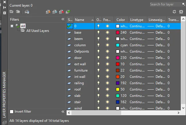
- Go to layer properties < create new layers < name the layers for reference < close.
Architectural drawings:-
- Plan
- Elevation
- Section
Structural drawings:
- Column Layout
- Footing Layout
- Beam Layout
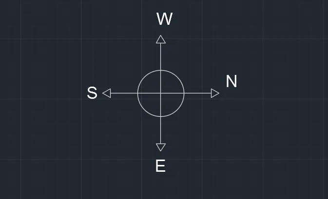
- Using the commands line and Dtext, i have created the directions.
- Then, Using the BLOCK command, i made it to a single block and named it as directions.
I. ARCHITECTURAL DRAWINGS:-
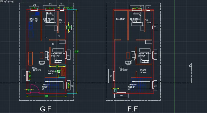
1. PLAN:-
- Using the line Command, i drew the plot boundary of 60'x20'.
- The building's main entrance is facing the East direction.
- Using the commands line, offset, fillet and trim.
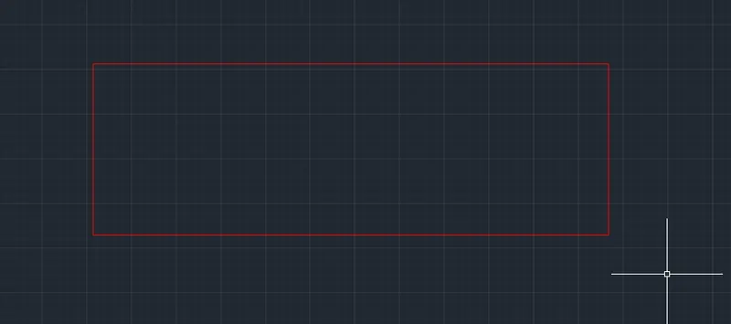
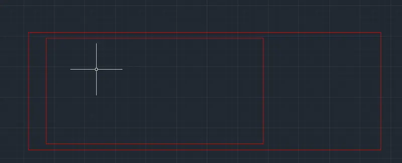
- After providing the offset distance, the floor dimensions comes about 45'x18' including walls,
- Outer walls at 9" thickness and inner walls at 4.5" thickness is provided,
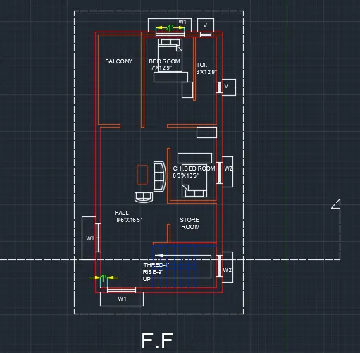
- Now, using the commands Line, polyline, offset, fillet and trim, I have created my own plan for the project,
- It is planned as per VASTHU.
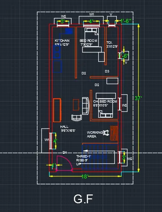
Ground floor:-
- Hall 9'6"×16'5"
- Mas. Bed room 7'×12'9"
- Chi.bed room 6'8"×10'5"
- Kitchen 5'9"×12'9"
- Toilet 3'×12'9"
- Working area 7'×5'"
First floor:-
- Hall 9'6"×16'5"
- Mas. Bed room 7'×12'9"
- Chi.bed room 6'8"×10'5"
- Kitchen 5'9"×12'9"
- Toilet 3'×12'9"
- Store room7'×5
- Balcony 6'2"×12'9"
Staircase:-
- Thred- 1'
- Rise -9"
Doors:-
- D1- 5'×7'
- D2- 3'×7'
- D3- 2'10"×6'6"
Windows /Ventilator:-
- W1- 4'×5'
- W2- 3'×4'
- V- 1'6"×1'6"
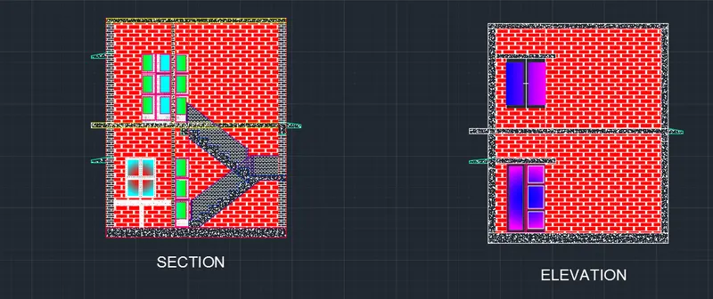
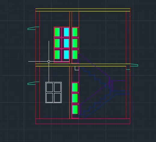
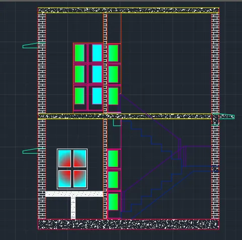
2. SECTION:
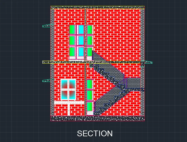
- Using the commands Line, polyline, offset, fillet and trim, I have created the sectional view for the Section
- Provided windows as per the plan, kitchen space as per plan and stairs as per plan.
- Provided lintel beam over the windows, doors.
- Provided Parapet wall and over head as well
- Using Hatch command, I have filled PLINTH BEAM with BRICK
3. ELEVATION:-
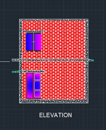
- Using the commands Line, polyline, offset, fillet, trim and hatch, I have created the sectional view for the Elevation.
- Provided windows as per the plan, and door as per plan.
- Provided lintel beam over the windows
- Provided Parapet wall
- Using Hatch command, I have filled super structure below parapet wall with BRICK and adjusted the scale for better visibility.
II. STRUCTURAL DRAWINGS:-
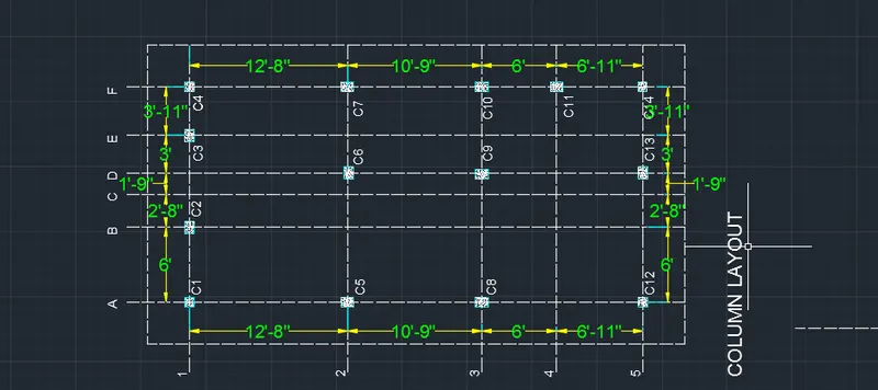
1. Column Layout:-
- Turn off all the layers except the column layer and boundary layer in the layer properties.
- Select the Copy tool by typing CO or COPY in the command box.
- Select all the columns from the building plan and copy them to a different location as shown in the figure below.
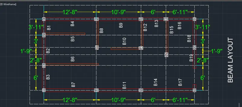
2. Beam Layout:-
- Turn off all the layers except the column layer and boundary layer in the layer properties.
- Select the Copy tool by typing CO or COPY in the command box.
- Select all the columns from the building plan and copy them to a different location as shown in the figure below
- Turn off all the layers except the column layer and boundary layer in the layer properties.
- Typing the tool by COPY in the command box
- Select all the columns from the building plan and copy them to a different location as shown in the figure below
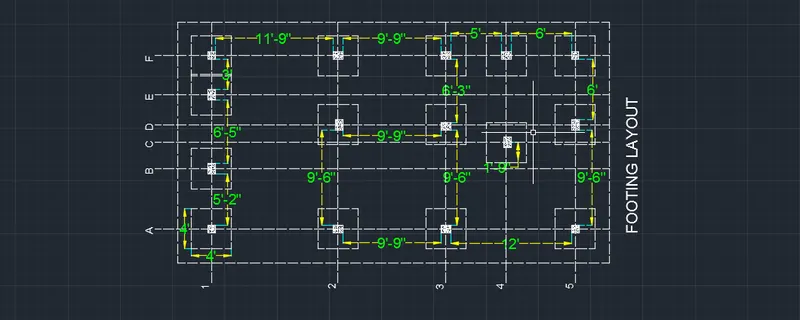
3. Footing layout:-
- Turn off all the layers except the column layer and boundary layer in the layer properties.
- Select the Copy tool by typing CO or COPY in the command box.
- Select all the columns from the building plan and copy them to a different location as shown in the figure below
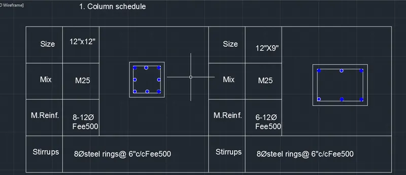
Column Schedule:-
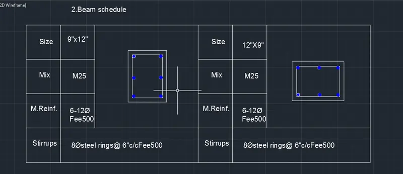
Beam Schedule:-
Footing Size:-
Footing size is 4'x4'.
RESULTS:-
Both Architectural and Structural drawings are shown below again.