Project 1 _Creating an Architectural plan for the provided plot size and develop relevant basic structural drawings
Aim: To draw residential building of dimension 60' x 20' with following drawings
1) architectural drawings
Plot drawings
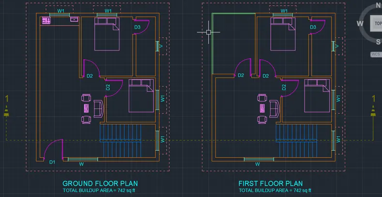
Ground floor plan
first floor plan
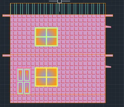
elevation view
2)structural drawings
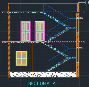
Section view
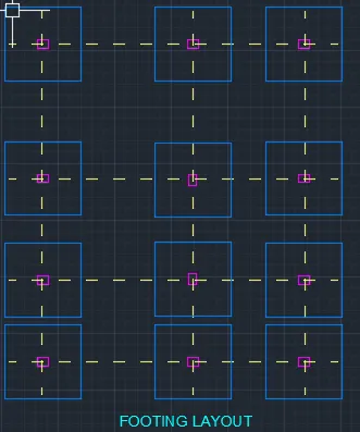
footing layout
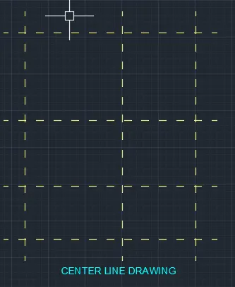
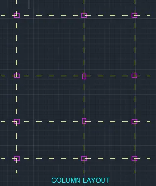
Column layout
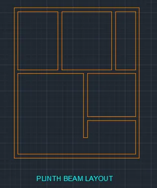
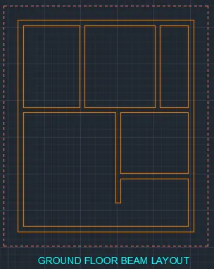
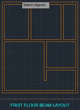
Beam layout
INTRODUCTION
- Residential building is drawn with plot dimension
- Plinth dimension are chosen as 30' x 18'
- G+1 floor is designed with inside staircase
- Building have Ground floor great room, kitchen, in Ground floor 2 bedrooms, staircase to 1st floor, first floor great room, in 1st floor 2 bedrooms, balcony, staircase to roof
- Building designed with Npmain door at North East facing and main gate at East North position,. Initially layers are created for all the composition of the house.
- Thickness of main wall 9"
- Thickness of internal wall 4.5"
- All columns size 9"×12"
- All the beam sizes 9"×9"
- Rebar specification
- 3 types doors are used
- Main door D1 4'×7'
- D2 door 3'6"×7'
- D3 door 3'×6'
- 2 types windows are used
- W size 6'×5'
- W1 size 4'×5'
- One ventilator is used 2'×2'
- Inner Staircase consists of 21 steps
- Thread 10" and raiser 6"
- Hand rails 2" in Dia and 3' height
Procedure
- Open Autocad
- Change units as required
- Set units in decimal and precision 0.00 and limits press enter
- Type D and change dimstyle
- Units command is used
- Dimstyle command is used
- Line command used to draw lines
- Trim command used to remove unwanted objects from drawings
- Rec command used to draw tables
- Dim command is used to give all dimension
- Offset command is used to get equal distance
- Circle command is used to draw circles
- Block command is used to save different names to different blocks
- Bedit command is used
- Insert command is used to insert the created blocks in drawing
- Attribute command is used edit the text inside the blocks
- Text command is used