Project 1 _Creating an Architectural plan for the provided plot size and develop relevant basic structural drawings
Design and Draft a layout of a residential building with the following details:
a. Plot Size: 60’x20’(18.3m x6m)
b. Orientation- Facing East
c. Develop the following: 1. Architectural Drawing (Floor Plan, Elevations, and Sections)
2. Structural Drawing (Column, Beam, Footing Plan)
AIM:
To Design and Draft a layout of a residential building with plot size 60' X 20' (18.3 m x 6 m).
Design and draft a Residential Building Facing EAST
Create Architectural Drawings- Floor plan, Sectional Plans and Elevations
Create Structural Drawings – Column, Footing and Beam
Commands Used:
- xl
- line
- offset
- trim
- Extension
- rectangle
- lt (linetype)
- ADC (design centre )
- arc
Procedure:
Set the units to ENGINEERING using UNITS command
Set the lower limit and upper limit of the screen using LIMITS command
Lower limit: 0’, 0’
Upper limit: 100’, 100’
Type Zoom
Select all and press Enter
Type XLINE
Select Vertical option and draw a vertical line
Type XLINE
Select Horizontal option and draw a horizontal line.
The two lines intersects and this point is the starting point.
Start from left and go to right.
Select LAYER properties dialogue box
Create New Layers
Select different COLOUR to each layer created.
Choose Line command to draw rooms as per vaastu.
Consider External wall thickness as 9” inches and internal wall thickness as 4” inches.
Select the OFFSET command for wall thickness
Use FILLET command for trimming wall corners
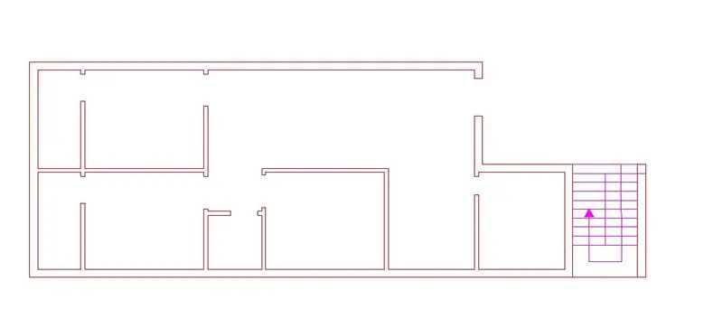
Select LAYER properties dialogue box
Create New Layers
Select different COLOUR to each layer created.
Locate Columns
Choose Line command to draw staircase.
Draw staircase with size of Thread- 10” inches
Assume Doors and Window sizes
W1= 6’ x 4’
W2= 4’ x 4
V= 2’ x 2’
D1= 3’-3”x 6’-8”
D2= 3’-0” x 6’-8”
D3= 2’-6”x 6’-8”
Draw Doors and Windows
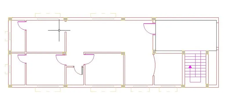
Draw lintels to these windows.
Change Linetype of the lintels to ISO DASH SPACE.
Change Line Scale if required.
Select ANNONTATE in Ribbon
Under TEXT dialogue box
Choose Multiline Text tool
Using MTEXT label the details
Select command: ‘_STYLE
Create new style with Font name - Arial and Font Style – Regular
Set current.
Select LAYER properties dialogue box
Create New Layers
Select different COLOUR to each layer created.
Set the TEXT as Current Layer
Write Text of all rooms.
In the Text Editor, use SPELL CHECK tool for any spell checks
Select ANNONTATE in Ribbon
Select LEADERS PALETTE
Choose MULTILEADER STYLE MANAGER
Create new style
Modify the Leader format, Leader structure, Content
And Set current.
Select LAYER properties dialogue box
Create New Layers
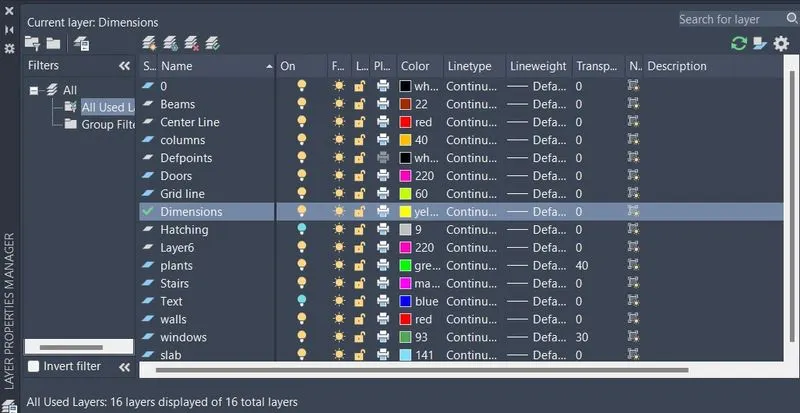
Set the Dimensions as Current Layer
Provide Dimensions
Use LEADERS command wherever required.
Select ANNONTATE in Ribbon
Under DIMENSION dialogue box
Select DIMLINEAR command to mark column dimensions, and then
Select DIMCONTINUE command to mark the distances
Select DIMBASELINE command to mark the distance from base to the respective object.
Use DIMBREAK command wherever dimension lines intersect.
In the command prompt type ADC( design centre ) to add the components.
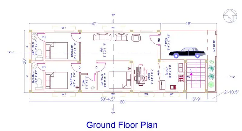
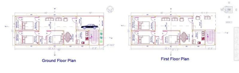
Copy Ground Floor and make slight changes for First Floor.
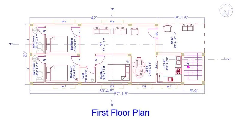
First Floor Plan
RESULT: -
By using DRAWING tools, MODIFY tools, ANNOTATE tools and LAYER properties we generated FLOOR PLANS.
Draw Section lines on the Plan to develop Sectional Drawings.
Two Sections
1) Section A-A
2) Section B-B
2]
- SECTIONAL DRAWINGS
AIM: -
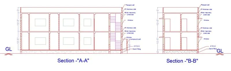
Create the section A-A
Use proper dimension techniques and dimension styles
Use Layers.
PROCEDURE: -
Select command: XLINE
Select vertical option
Turn on the OBJECT SNAP
Wherever the Section cuts project the lines of objects from the floor plan using XLINE command.
Draw a Horizontal Line. This is G.L
Provide Elevation Height as 10'-5" units
Using OFFSET tool with offset distance as 10'-5" draw roof slab
Using OFFSET tool with offset distance as 5" draw roof slab thickness.
Provide slab thickness as 5" INCH
After drawing, use MODIFY tools
Use TRIM command to trim the extended lines.
Use EXTEND command to the extend the required lines.
Use OFFSET command to provide thickness to slabs shades etc.
Use FILLET command to trim the corners.
After finishing the G.L floor details.
Provide height of 10'-5" units for 1st floor
Project Columns ,Doors, Windows and Stairs from floor plan.
Using XLINE and OBJECT SNAP project windows each room from floor plan.
Provide height to Windows
Select LAYER properties dialogue box
Draw PARAPET WALL
Project walls from plan and provide height and thickness to walls.
Draw windows to the outer wall and provide sun shades on both sides of outer walls if required.
Repeat the same procedure of 1st flOOR
Use COPY command to draw the 1ST FLOOR
Provide 3' units height of parapet wall on top of 1ST floor

Select ANNONTATE in Ribbon
Under TEXT dialogue box
Choose Multiline Text tool
Using MTEXT label the details
Select command: ‘_STYLE
Create new style with Font name - Arial and Font Style – Regular
Set current.
Write Text of all floors.
In the Text Editor, use SPELL CHECK tool for any spell checks
Select ANNONTATE in Ribbon
Select LEADERS PALETTE
Choose MULTILEADER STYLE MANAGER
Create new style
Modify the Leader format, Leader structure, Content
And Set current.
Use LEADERS command wherever required.
Select ANNONTATE in Ribbon
Under DIMENSION dialogue box
Select DIMLINEAR command to mark dimensions, and then
Select DIMCONTINUE command to mark the distances.
Select DIMBASELINE command to mark the distance from base to the respective object.
Use DIMBREAK command wherever dimension lines intersect.
Set the Dimensions as Current Layer
Provide Dimensions to each floor and wall thickness.
RESULT:-
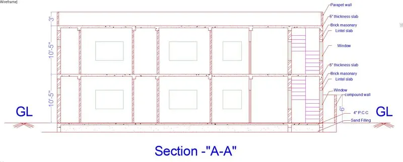
By using DRAWING tools, MODIFY tools, ANNOTATE tools and LAYER properties and by generating projections from Floor plan we generated SECTIONAL DRAWING "A-A"
SECTION B-B
AIM: -
Create the section B-B
Use proper dimension techniques and dimension styles
Use Layers.
PROCEDURE: -
Select command: XLINE
Select vertical option
Turn on the OBJECT SNAP
Wherever the Section cuts project the lines of objects from the floor plan using XLINE command.
Draw a Horizontal Line. This is G.L
Type XLINE
Project Floor plan details to draw Section B-B
Provide Elevation Height as 10'-1" units
Using OFFSET tool with offset distance as 10'-5" draw roof slab
Using OFFSET tool with offset distance as 5" draw roof slab thickness.
Provide slab thickness as 5" INCH
After drawing, use MODIFY tools
Use TRIM command to trim the extended lines.
Use EXTEND command to the extend the required lines.
Use OFFSET command to provide thickness to slabs shades etc.
Use FILLET command to trim the corners.
After finishing the G.L floor details.
Provide height of 10'-5" units for 1st floor
Repeat the same procedure of 1st flOOR
Use COPY command to draw the 1ST FLOOR
Project Door and columns from floor plan.
Using XLINE and OBJECT SNAP project windows of each room from floor plan.
Provide height to windows
Project walls from plan and provide height and thickness to walls.
Provide 3' units height of parapet wall on top of 1ST floor
RESULT:-
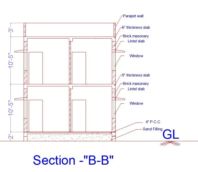
By using DRAWING tools, MODIFY tools, ANNOTATE tools and LAYER properties and by generating projections from Floor plan we generated SECTIONAL DRAWING "B-B"
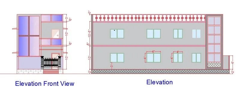
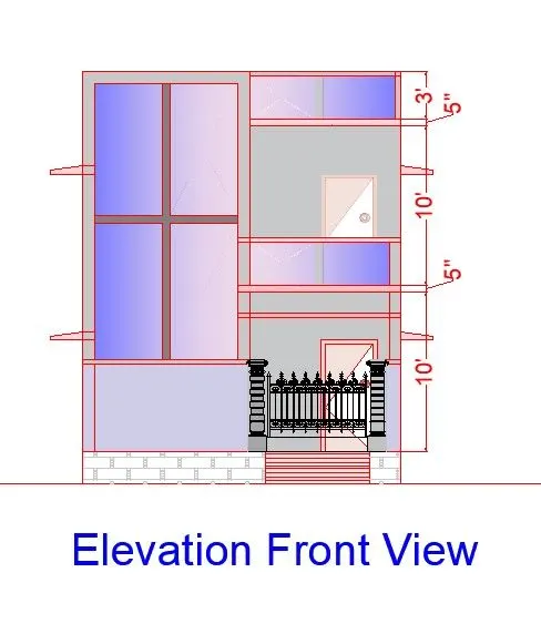
3]Side ELEVATION
AIM: -
Create the FRONT ELEVATION
Use proper dimension techniques and dimension styles
Use Layers.
PROCEDURE: -
Select command: XLINE
Select vertical option
Turn on the OBJECT SNAP
Wherever the Section cuts project the lines of objects from the floor plan using XLINE command.
Draw a Horizontal Line. This is G.L
Type XLINE
Project Floor plan details to draw Front Elevation.
Provide Elevation Height as 10'-5" units for each floor
Using OFFSET tool with offset distance as 10'-5" draw roof slab
Using OFFSET tool with offset distance as 5" to draw slab
After drawing, use MODIFY tools
Use TRIM command to trim the extended lines.
Draw windows to the outer wall and provide sun shades on both sides of outer walls
Project Windows from floor plan.
Select ANNONTATE in Ribbon
Under TEXT dialogue box
Choose Multiline Text tool
Using MTEXT label the details
Select command: ‘_STYLE
Create new style with Font name - Arial and Font Style – Regular
Set current.
Write Text of all floors.
Select ANNONTATE in Ribbon
Select LEADERS PALETTE
Use LEADERS command wherever required.
Select ANNONTATE in Ribbon
Under DIMENSION dialogue box
Select DIMLINEAR command to mark dimensions.
Select DIMCONTINUE command to mark the distances
Select DIMBASELINE command to mark the distance from base to the respective object.
Use DIMBREAK command wherever dimension lines intersect.
By hatching components for better windows, walls.
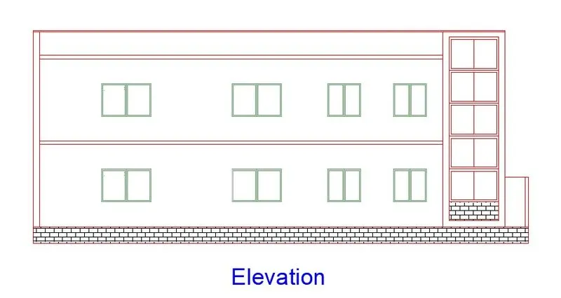
RESULT: -By projecting the floor details we generated Side Elevation showing with dimensions and details.
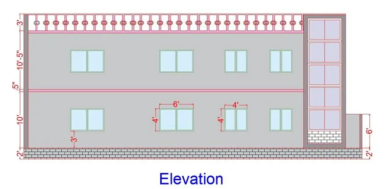
ELEVATION
AIM: -
Create the ELEVATION
Use proper dimension techniques and dimension styles
Use Layers.
PROCEDURE: -
Select command: XLINE
Select vertical option
Turn on the OBJECT SNAP
Wherever the Section cuts project the lines of objects from the floor plan using XLINE command.
Draw a Horizontal Line. This is G.L
Type XLINE
Project Floor plan details to draw Front Elevation.
Provide Elevation Height as 10'-5" units for each floor
Using OFFSET tool with offset distance as 10'-5" draw roof slab
Using OFFSET tool with offset distance as 5" to draw shades
After drawing, use MODIFY tools
Use TRIM command to trim the extended lines.
Draw windows to the outer wall and provide sun shades on both sides of outer walls
Select ANNONTATE in Ribbon
Under TEXT dialogue box
Choose Multiline Text tool
Using MTEXT label the details
Write Text of all floors.
Select ANNONTATE in Ribbon
Select LEADERS PALETTE
Use LEADERS command wherever required.
Select ANNONTATE in Ribbon
Under DIMENSION dialogue box
Select DIMLINEAR command to mark dimensions.
Select DIMCONTINUE command to mark the distances
Select DIMBASELINE command to mark the distance from base to the respective object.
By using hatching to the elevation for better appereance.
RESULT: -
By projecting the floor details we generated Elevation showing with dimensions and details.
2. Structural Drawings
Procedure:
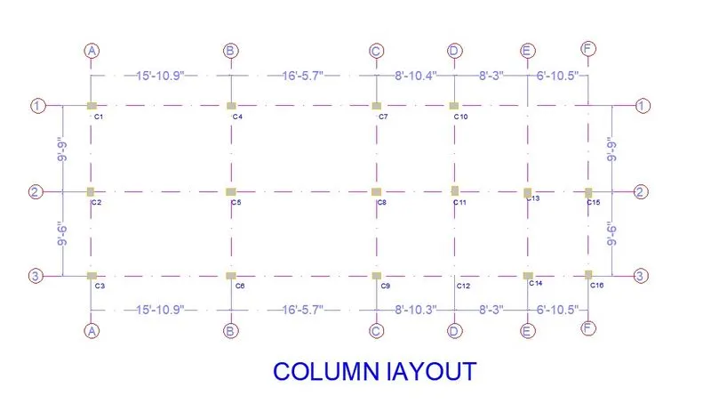
(a) Column Layout:
STEP 1 Turn off all the layer except the column layer.
Enter CO, Select all the columns from the building plan and copy it to a different location.
Press Esc.
Turn on all the layers.
Select the Construction Line tool by entering 'XLINE command in the command tab Enter V.
Draw lines through the mid-point of the columns.
Enter XL in the command prompt and Click on H.
Draw lines through the mid-point of the columns. Press Esc
Select the Trim tool by entering TR command in the command tab.
Press ENTER Select Edge option, and click on No Extend.
Related Select the extruted lines
Press Esc to cancel the TRIM command.
Select the lines, right click, go to properties and change the line type to ACAD_ISO02W100.
Select the Dimension tool by entering DIM in the command line.
Select the first point and second point of the object to be measured, then drog the diamention line to the desired.
location. Repeat for all the objects to be measured.
Enter 'MTEXT' command in the command line.
Specify the start point of text as required.
Scale the text to the desired size. Copy the text box to wherever necessary.
Enter ED in the command promt and edit the text boxes as required.
Click Enter and press Esc.
RESULT: Column layout is show with detail dimensions below.
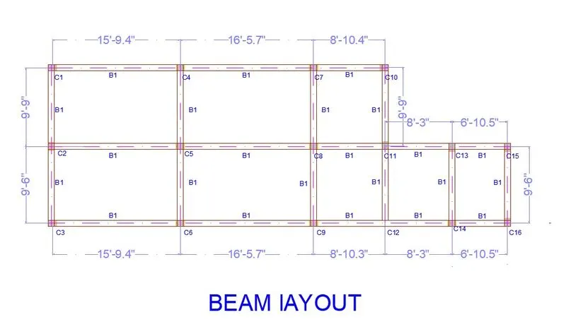
(b) Beam Layout:
Enter CO, Select all the column layout and copy it to a different location.
Press Esc.
Select the Offset tool by entering OFFSET command in the command tab
Specify offset distance as 4.5" and Create offsets for the beam of width 9"
Press Esc.Press Esc.Select the Trim tool by entering TR command in the command tab
Select Edge option; and click on No Extend.
Select the unwanted lines
Press 'Esc' to cancel the TRIM command.
Select the Dimension tool by entering DIM in the command line
Select the first point and second point of the object to be measured, then drag the dimension line to the desired location. Repeat for all the objects to be measured.
Enter 'MTEXT command in the command line.
Specify the start point of text as required.
Copy the text box to wherever necessary.
Enter ED in the command promt and edit the text boxes as required.
Click Enter and press Esc.
Result:
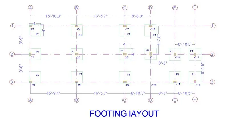
(c) Footing Plan:
Enter CO, select the column layout plan at different loaction.
Select the Rectangle tool from the ribbon.
Draw rectangle of size @4' X 4' for footing for all columns.
Press Esc
Selec the Dimension And Text layer.
Select the Dimension tool by entering 'DIM' in the command line.
Select the first point and second point of the object to be measured, then drag the dimension line to the desired location. Repeat for all the objects to be measured.
Enter 'MTEXT command in the command line.
Specify the start point of text as required. Copy the text box to wherever necessary.
Enter ED in the command promt and edit the text boxes as required. Click Enter and press Esc.
Save the Drawing.
Footings shall provided on considering the site size and condition as per plan.
RESULT: