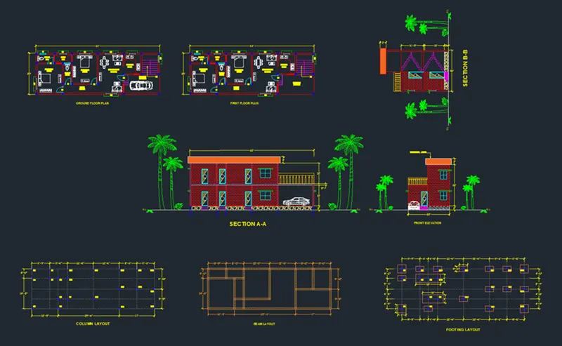
Project 1 _Creating an Architectural plan for the provided plot size and develop relevant basic structural drawings
Design and Draft a layout of a residential building with the following details:
a. Plot Size: 60’x20’(18.3m x6m)
b. Orientation- Facing East
c. Develop the following: 1. Architectural Drawing (Floor Plan, Elevations, and Sections) 2. Structural Drawing (Column, Bean, Footing Plan)
AIM:
Design and Draft a Layout of Architectural Drawings for a plot size of 60'x20', facing East, and develop relevant structural drawings.
INTRODUCTION:
The Desired Drawings of Floor plan, Elevations, and Sections are Sketched in Autocad using various tools. The Step by step procedure of drawings is explained in detail with diagrams
Details provided are:
Plot size: 60'x20'
Orientation: East Facing
ARCHITECTURAL DRAWINGS
(A) Floor Plan:
Commands Used:
Units
Limits
Layer Properties
XLine
Line
Rectangle
Arc
Trim
Offset
Rotate
Copy
Move
Hatch
Mtext
Dimension
Tool Pallette
Procedure:
Step 1:
Go to the Application Menu and select New
In the startup dialog box set Feet Inchesas the default settings
Type UNand set the units as Architecturaland precision as 0.0
Set the units as Inchesin the insertion scale
Type Limitsin the command box and set the lower limit as 0,0and upper limit as 80',80'
Type Z enter for Zoom and A for Zoom all
Step 2:
Select LayerPropertiesby typing Layer in the command box
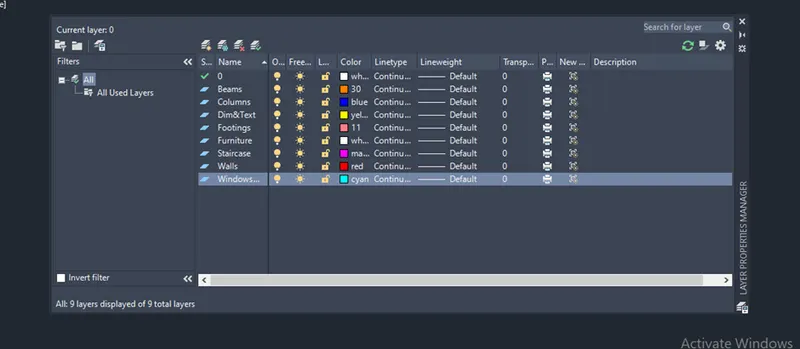
Click on a new layer to create the following layers (i.e., Doors and windows, External Wall, Internal Wall, Stairs, Furniture, Slab, Dimensions, and Text)
Specify different colors for different layers to identify each layer easily and then close the layer properties manager
Step 3:
Select the Exterior wall as the default layer in the layer panel
Select the XLinetool by typing XL or XLine in the command box
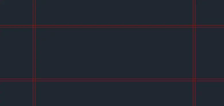
Draw two lines ( i.e., horizontally and vertically ) both intersecting at a 90-degree point, and then press Esc to cancel the XLine
Select the Trimtool and trim the unnecessary lines and press enter
Select the Offsetcommand and give the offset distance as 9"
Select both the vertical and horizontal lines and Offset them inside
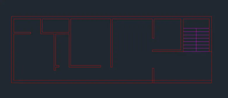
Similarly using the Offsetcommand create the sketch that is shown in the figure below
Step 4:
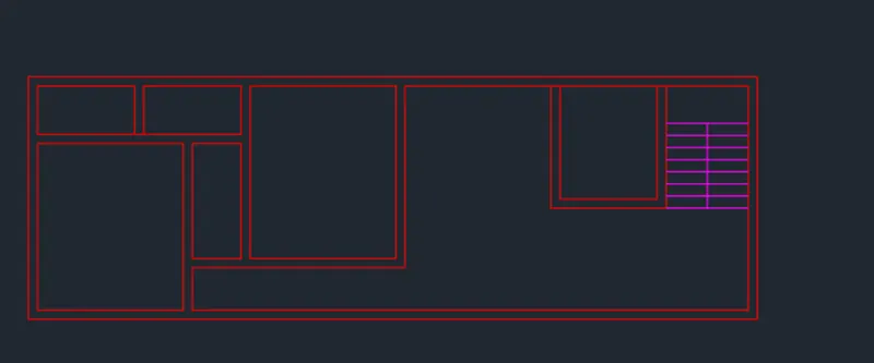
After Creating External walls, now we have to create internal walls using the Offset command
By using the Offsetcommand create the internal walls with a thickness of 9"
Specify the offset distance, select the line to offset, and click on the direction that we need to offset
Press Escto cancel the line command
The new lines that we have drawn are selected and assigned to the internal wall layer
By using the Trimcommand and ExtendCommand, trim the unwanted lines and extend the lines that need to extend respectively
Step 5:
Now we have to draw a staircase using staircase layer property
Select the Linetool and draw a length of 9'10"at the entry point of the building
Select the Offsetcommand and give the offset distance as 4', then offset it through the desired side
Draw a line through the midpoint of the lines created previously to divide the stairs and press Escto cancel the line command
Select the Offsettool and give the offset distance as 1'and offset it through the desired side
By using the Linecommand, draw a line through the midpoint of the lines that we created earlier to divide the stairs
By using the Trimcommand, trim the unnecessary lines
Step 6:
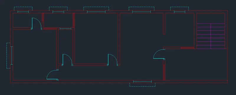
After creating External and Internal walls, Now we have to draw doors and windows using the doors and windows layer
Select the Linetool by typing L or Line in the command box
Draw doors at the specified positions by using the Line tool and draw a swing of that door by using the Arc tool
Door D1is created at the entrance with a width of 3'
Door D2is created at the entrance with a width of 3'
Now we have to draw windows by using a door and window layer
Draw windows by using the Line command
Window W1is created with a width of4'
Window W2is created with a width of 3'
Ventilator V1is created with a width of 3'
By using CopyCommand, Copy Windows and move to the required position
Step 7:
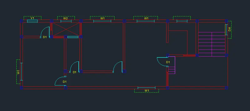
After creating external and internal walls, now we have to give column marking
Select the column layer in the layer properties
Select the Linetool by typing L or Line in the command box
Draw a column of dimension 9"×9"and press Escto cancel the Line Command
Select the Copytool and copy the column created before to the desired locations as shown in the figure below
Select the Hatchtool by typing H or Hatch in the command box
Select Hatch type as pattern, give hatch type as AR-Concrete,and pick points inside the column
Select the Trimtool and trim the unnecessary lines
Step 8:
Select the Furniture layer as the default layer in the layer panel
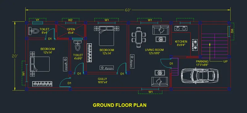
By using Tool Palletesand other DWG Drawings, Place the Furniture and Car in the desired locations as shown in the figure below
Select the dimension and text layer as the default layer in the layer panel
Enter DS in the command box to open the dimension style manager dialog
Modifythe dimensions as per the requirement
Change the color of the dimension and extension line as per the requirement
Under the text option, Change the text height to 8"
click ok, then click set current and close the dimension style manager dialog box
Give dimensions and text as per the drawing and requirement using the Mtextcommand and DimensionCommand
Step 9:
Select the Copytool by typing COin the command box
Select the Ground Floor plan and copy it to the another location
Delete the Parking area at the main entrance
Edit the dimensions whenever required and edit the text boxes by using EDCommand
Select the Linetool from the ribbon tab, draw a line for the parapet wall for the balcony on the first floor
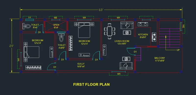
Result:
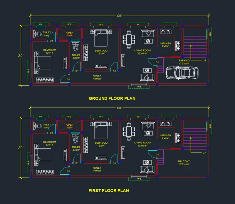
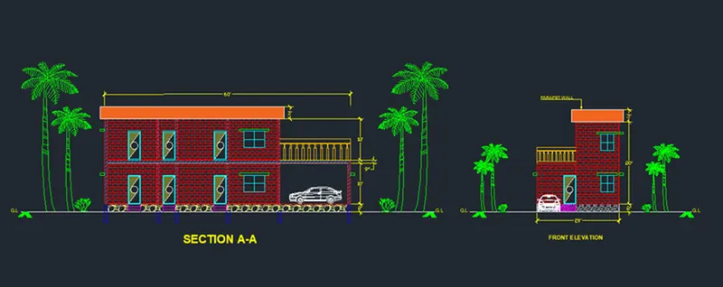
(B) Elevation:
Commands Used:
Units
Limits
Layer Properties
XLine
Line
Rectangle
Arc
Trim
Offset
Rotate
Copy
Move
Hatch
Mtext
Dimension
Tool Pallette
Procedure:
Step 1:
Select the Construction line by typing XLor XLinein the command box
Draw the projection lines from the ground floor plan created and draw a horizontal line at a suitable distance
Select the Trimcommand and trim the unnecessary lines
Select the Offsettool by typing O or Offset in the command box
Offset the horizontal line to a distance of 2'for the plinth height
Offest the previous horizontal line again to a distance of 10'for the floor height
The horizontal X lines are offset to a distance as per the given room dimensions and wall thickness
Select the Trimtool by typing TR or Trim in the command box
Trim the unnecessary lines and press Esc to cancel the trim command
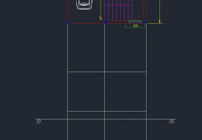
Step 2:
Select the Offest tool by typing O or Offset in the command box
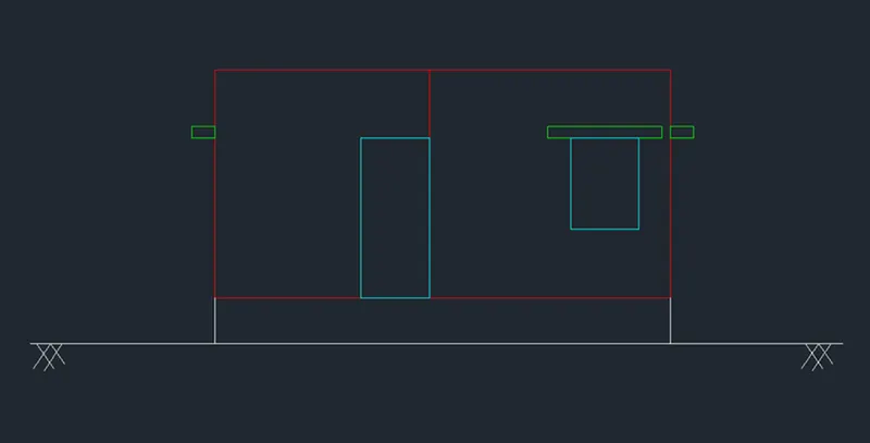
Give the offset distance as 3'from the plinth height and 4'from the previous line
Select the Offsettool again and give the Offset distance as 6"
Offset the Previous line to the above for the lintel height
By using the Rectangularcommand, Draw the doors, windows, and lintels as shown in the figure below
Using the Trimcommand, trim the unnecessary lines and press Esc to cancel the trim command
Step 3:
Select the XLinetool by typing XL or XLine in the command box
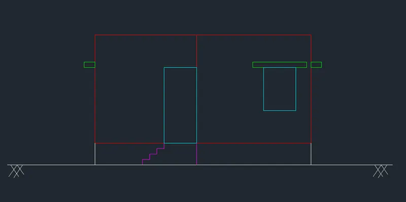
Draw vertical projection lines of the staircase from the plan created
Select the Trimcommand and trim the unnecessary lines
Select the Offsettool by typing O or Offset in the command box
Give the Offset distance as 8"and offset the ground level line to the plinth level for 3 segments
By using the Linecommand, Draw the staircase of tread 1'and rise 8" as shown in the figure below
Step 4:
Select the XLinetool by typing XL or XLine in the command box
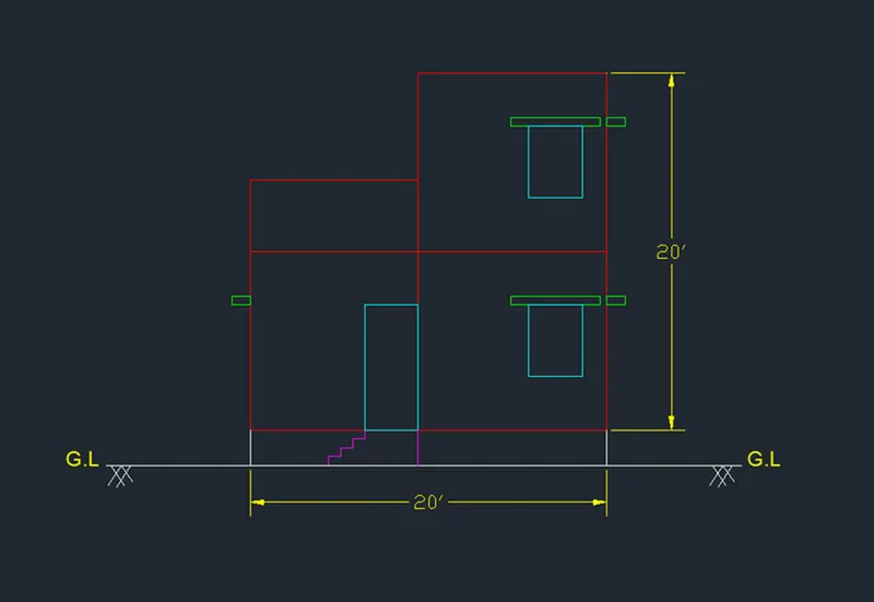
Draw vertical projection lines from the first-floor plan created and draw a horizontal line at a suitable distance
Select the Trimcommand and trim the unnecessary lines
Select the Offsettool by typing O or Offset in the command box
Draw the doors and windows using projected lines similarly as we drew for the ground floor plan
By using Copy Command, Copy the First Floor plan and Move to the top of the ground floor plan as shown in the figure below
Step 5:
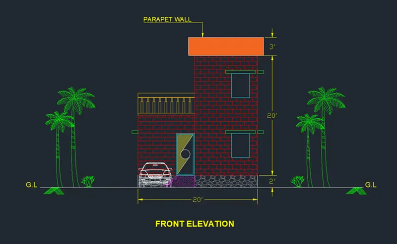
By using the Line command, Draw a parapet wall at the top of the first-floor plan
Similarly draw the balcony for the first-floor plan as shown in the figure below
Select the Hatchtool, Select AR-B816Cas the hatch pattern, and pick the point inside the building
Select the Furniture layer as the default layer in the layer panel
By using Tool Palletesand other DWG Drawings, Place the Furniture and Car in the desired locations as shown in the figure below
Enter DSin the command box to open the dimension style manager dialog
Modify the dimensions as per the requirement
Change the color of the dimension and extension line as per the requirement
Under the text option, Change the text height to 8"
click ok, then click set current and close the dimension style manager dialog box
Give dimensions and text as per the drawing and requirement using the Mtextcommand and DimensionCommand
Result:
(C) Section A-A:
Commands Used:
Units
Limits
Layer Properties
XLine
Line
Rectangle
Arc
Trim
Offset
Rotate
Copy
Move
Hatch
Mtext
Dimension
Tool Pallette
Procedure:
Step 1:
Select the Construction line by typing XLor XLinein the command box
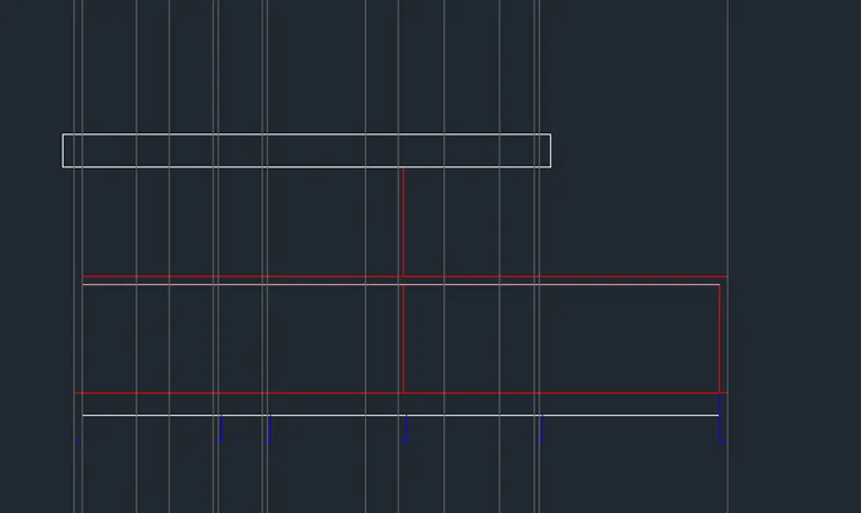
Draw the projection lines from the ground floor plan created and draw a horizontal line at a suitable distance
Select the Trimcommand and trim the unnecessary lines
Select the Offsettool by typing O or Offset in the command box
Offset the horizontal line to a distance of 2'for the plinth height
Offest the previous horizontal line again to a distance of 10'for the floor height
The horizontal X lines are offset to a distance as per the given room dimensions and wall thickness
Select the Trimtool by typing TR or Trim in the command box
Trim the unnecessary lines and press Esc to cancel the trim command
Step 2:
Select the XLinetool by typing XL or XLine in the command box
Draw vertical projection lines from the first-floor plan created and draw a horizontal line at a suitable distance
Select the Trimcommand and trim the unnecessary lines
Select the Offsettool by typing O or Offset in the command box
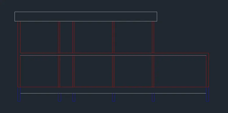
By using CopyCommand, Copy the First Floor plan and Move to the top of the ground floor plan as shown in the figure below
By using the Linecommand, Draw a parapet wall at the top of the first-floor plan
Step 3:
Select the Offesttool by typing O or Offset in the command box
Give the offset distance as 3'from the plinth height and 4'from the previous line
Select the Offsettool again and give the Offset distance as 6"
Offset the Previous line to the above for the lintel height
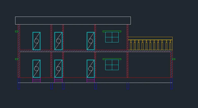
By using the Rectangularcommand, Draw the doors, windows, and lintels as shown in the figure below
Using the Trimcommand, trim the unnecessary lines and press Escto cancel the trim command
By using the Linecommand, draw the balcony for the first-floor plan as shown in the figure below
Select the Hatchtool, Select ANSI32as the hatch pattern, and pick the point inside the building.
Step 4:
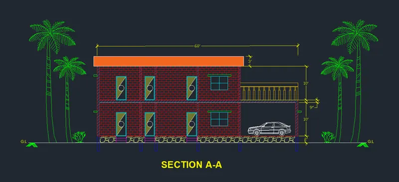
Select the Hatchtool, Select AR-B816Cas the hatch pattern, and pick the point inside the building
Select the Furniture layer as the default layer in the layer panel
By using Tool Palletesand other DWG Drawings, Place the Furniture and car in the desired locations as shown in the figure below
Enter DSin the command box to open the dimension style manager dialog
Modifythe dimensions as per the requirement
Change the color of the dimension and extension line as per the requirement
Under the text option, Change the text height to 8"
click ok, then click set current and close the dimension style manager dialog box
Give dimensions and text as per the drawing and requirement using the Mtextcommand and DimensionCommand
Result:
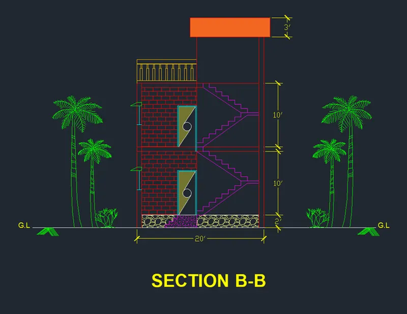
(D) Section B-B:
Commands Used:
Units
Limits
Layer Properties
XLine
Line
Rectangle
Arc
Trim
Offset
Rotate
Copy
Move
Hatch
Mtext
Dimension
Tool Palettes
Procedure:
Step 1:
Select the Construction line by typing XLor XLinein the command box
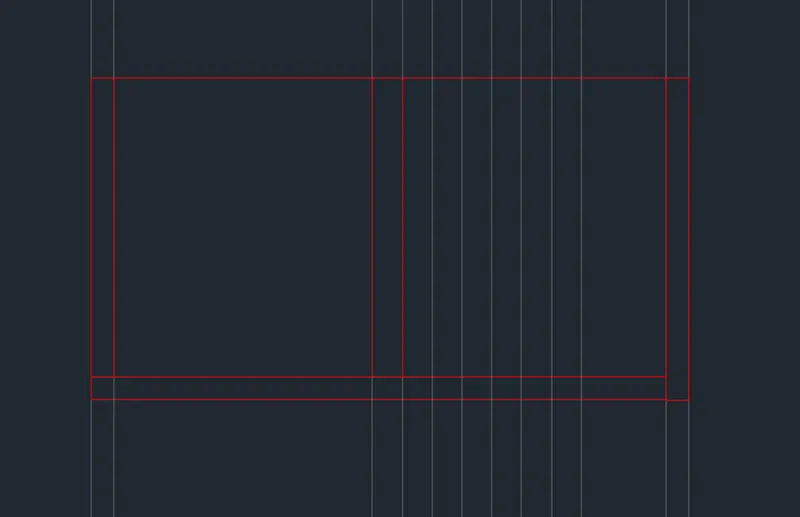
Draw the projection lines from the ground floor plan created and draw a horizontal line at a suitable distance
Select the Trimcommand and trim the unnecessary lines
Select the Offsettool by typing O or Offset in the command box
Offset the horizontal line to a distance of 2'for the plinth height
Offest the previous horizontal line again to a distance of 10'for the floor height
The horizontal X lines are offset to a distance as per the given room dimensions and wall thickness
Step 2:
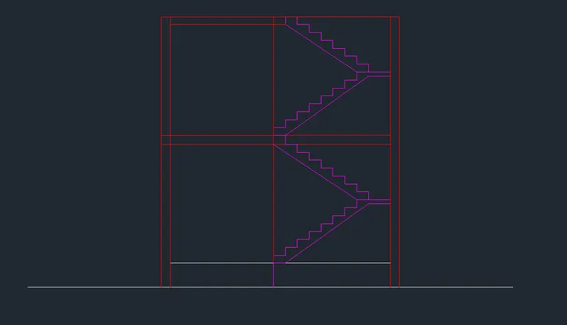
Select the Linetool by typing L or Line in the command box
Draw stairs having a rise of 8"and tread of 12"
Select the Copytool by typing CO or COPY in the command box
Copy the stairs one time to create the flight of stairs and Press Esc
Select the flight of stairs created and assign it to the stairs layer as shown in the figure below
Step 3:
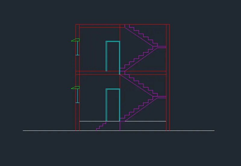
Select the Offesttool by typing O or Offset in the command box
Give the offset distance as 3'from the plinth height and 4'from the previous line
Select the Offset tool again and give the Offset distance as 6"
Offset the Previous line to the above for the lintel height
By using the Rectangularcommand, Draw the doors, windows, and lintels as shown in the figure below
Using the Trimcommand, trim the unnecessary lines and press Esc to cancel the trim command
Step 4:
Select the Hatchtool, Select AR-B816Cas the hatch pattern, and pick the point inside the building
Select the Furniture layer as the default layer in the layer panel
By using Tool Palletesand other DWG Drawings, Place the Furniture and car in the desired locations as shown in the figure below
Enter DSin the command box to open the dimension style manager dialog
Modifythe dimensions as per the requirement
Change the color of the dimension and extension line as per the requirement
Under the text option, Change the text height to 8"
click ok, then click set current and close the dimension style manager dialog box
Give dimensions and text as per the drawing and requirement using the Mtextcommand and DimensionCommand
Result:
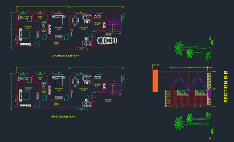
2.STRUCTURAL DRAWINGS:
(A) Column Layout:
Commands Used:
Copy
Xline
Trim
Dimension
Mtext
Procedure:
Step 1:
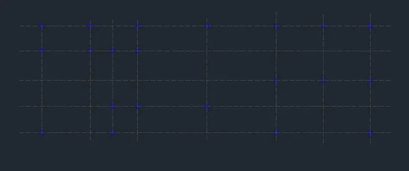
Turn off all the layers except the column layer in the layer properties
Select the Copytool by typing CO or COPY in the command box
Select all the columns from the building plan and copy them to a different location as shown in the figure below

Step 2:
Select the Construction line tool by typing XLor XLinein the command box
Select the line type as ISO 02W100and give scale as per requirement
Draw lines through the midpoint of the columns in the horizontal and vertical directions as shown in the figure below
Select the Trimtool by typing TR or Trim in the command box
Trim the unnecessary lines and press Escto cancel the trim command
Step 3:
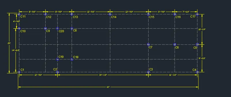
Select the Dimension tool by typing DIMin the command box
Select the first point and the second point of the object to measure. Repeat for all the objects to be measured
Enter DSin the command box to open the dimension style manager dialog
Modifythe dimensions as per the requirement
Change the color of the dimension and extension line as per the requirement
Under the text option, Change the text height to8"
click ok, then click set current and close the dimension style manager dialog box
Give dimensions and text as per the drawing and requirement using the Mtextcommand and DimensionCommand
Result:
(B) Beam Layout:
Commands Used:
Copy
Xline
Trim
Offset
Dimension
Mtext
Layer properties
Procedure:
Step 1:
Turn off all the layers except the column layer in the layer properties
Select the Copytool by typing CO or COPY in the command box
Select all the columns from the building plan and copy them to a different location as shown in the figure below
Step 2:
Select the Construction line tool by typing XLor XLinein the command box
Select the line type as ISO 02W100and give scale as per requirement
Draw lines through the midpoint of the columns in horizontal and vertical directions as shown in the figure below
Select the Trimtool by typing TR or Trim in the command box
Trim the unnecessary lines and press Escto cancel the trim command
Step 3:
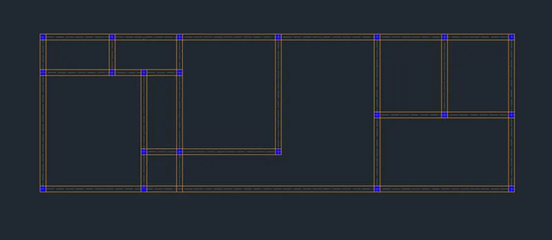
Select the Offsettool by typing O or Offset in the command box
Specify offset distance as 4.5"and create offsets for the beam of width 9"and then press Esc
Select the Offsettool again by typing O or Offset in the command box
Specify Offset distance as 3"and create offsets for the beam of width 6"and then press Esc
Select the Trimtool by typing TRor Trim in the command box
Trim the unnecessary lines and press Esc to cancel the command
Assign the beamlines to the beam Layer
Step 4:
Select the Dimension tool by typing DIMin the command box
Select the first point and the second point of the object to be measured. Repeat for all the objects to be measured
Enter DSin the command box to open the dimension style manager dialog
Modifythe dimensions as per the requirement
Change the color of the dimension and extension line as per the requirement
Under the text option, Change the text height to8"
click ok, then click set current and close the dimension style manager dialog box
Give dimensions and text as per the drawing and requirement using the Mtextcommand and DimensionCommand
Result:
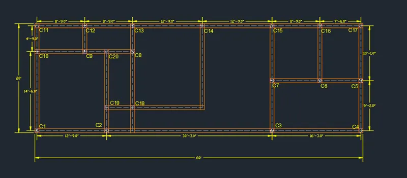
(C) Footing Layout:
Commands Used:
Copy
Xline
Rectangle
Trim
Dimension
Mtext
Layer properties
Procedure:
Step 1:
Turn off all the layers except the column layer in the layer properties
Select the Copytool by typing CO or COPY in the command box
Select all the columns from the building plan and copy them to a different location as shown in the figure below
Step 2:
Select the Construction line tool by typing XLor XLinein the command box
Select the line type as ISO 02W100and give scale as per requirement
Draw lines through the midpoint of the columns in the horizontal and vertical directions as shown in the figure below
Select the Trimtool by typing TR or Trim in the command box
Trim the unnecessary lines and press Escto cancel the trim command
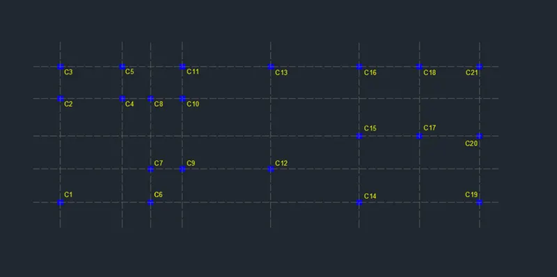
Step 3:
Select the Rectangletool by typing RECin the command box
Draw a rectangle of size @2'6",4'
Select the Copytool by typing CO or COPY in the command box
Copy the rectangle and place it in the columns C2, C5, C6, C11, C12, C13, C14, C15, C16, C17 C18,and C20at the desired locations
Select the Rectangletool again by typing RECin the command
Draw a rectangle of size @4',4'
Select the Copytool by typing CO or COPY in the command box
Copy the rectangle and place it in the columns C1, C3, C19,and C21at the desired locations
Select the Rectangletool again by typing RECin the command box
Draw a rectangle of size @12',4'
Select the Copytool by typing CO or COPY in the command box
Copy the rectangle and place it in the columns C4-C8-C19at the desired locations
Draw a rectangle of size @10',4'
Select the Copytool by typing CO or COPY in the command box
Copy the rectangle and place it in the columns C7-C9
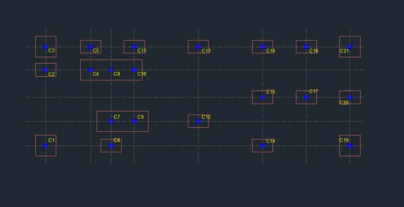
Step 4:
Select the Dimensiontool by typing DIMin the command box
Select the first point and the second point of the object to be measured. Repeat for all the objects to be measured
Enter DSin the command box to open the dimension style manager dialog
Modifythe dimensions as per the requirement
Change the color of the dimension and extension line as per the requirement
Under the text option, Change the text height to 8"
click ok, then click set current and close the dimension style manager dialog box
Give dimensions and text as per the drawing and requirement using the Mtextcommand and DimensionCommand
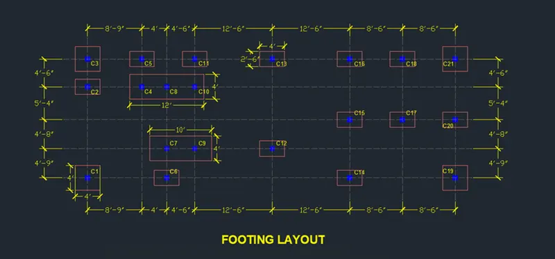
Result: