Project 1 _Creating an Architectural plan for the provided plot size and develop relevant basic structural drawings
CREATING AN ARCHITECTURAL PLAN FOR THE PROVIDED PLOT SIZE AND DEVELOP RELEVANT BASIC STRUCTURAL DRAWINGS
AIM-
TO DESIGN AND DRAFT AN ARCHITECTURAL PLAN FOR THE PROVIDED PLOT SIZE AND DEVELOP RELEVANT BASIC STRUCTURAL DRAWINGS
INTRODUCTION-
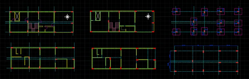
The plan is drafted using AutoCAD software in the given plot size.The main purpose of these project is to understand the process of design. The project content the plan of ground floor and first floor ,Elevation and section, Column layout and beam plan, center line and footing layout.The comand used for making the drawing is given below as well as all the step are mention with pictures which is drafted and taken from AutoCAD
TOOLS USED-
- LINE - Command for line is L
- CONSTRUCTTION LINE - Command for construction line is XL
- TRIM - Command for trim is TR
- TEXT- Command for text is DTEXT/MTEXT
- DIMENSION - Command for line is Dimension DIM
- OFFSET - Command for offset is O
- FILLET - Command for fillet is F
- SPLINE - Command for spline is SPL
- LAYERS -Command for layer is LA
- CIRCLE - Command for circle is C
- RECTANGLE - Command for the rectangle is REC
- HATCH - Command for hatch is H
- ARC - Command for arc is A
DEATAILS-
- PLOT SIZE - 60' X 20'
- ORIENTATION - FACING EAST
PROCEDURE-
STEP 1
- Go to START MENU, and select AutoCAD.
- The User Interface of AutoCAD is OPEN.
- Click the start Drawing tab
- The workspace of AutoCad is open,
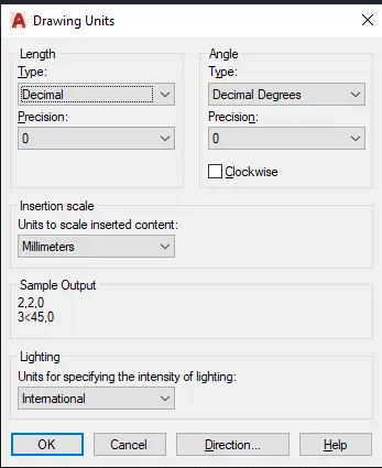
- Enter UNITS in the command box.
- Select DECIMAL in TYPE, 0 in PRECISION, and MILLIMETER in UNITS TO SCALE INSERTED CONTENT.
- Select Angle type as DECIMAL DEGREE, and precision is 0 and direction are Anti-clockwise.
- Press OK.
STEP 2
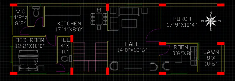
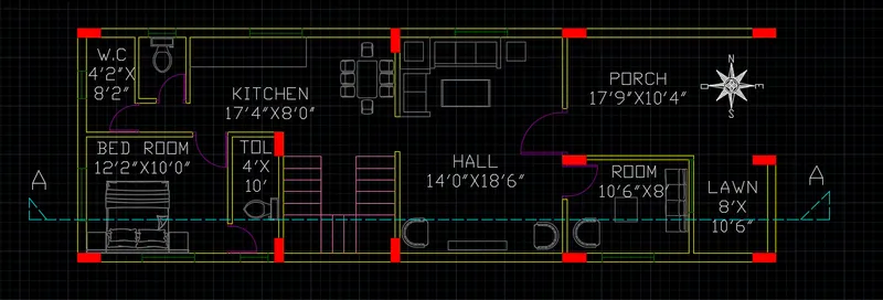
- CREATING OF GROUND FLOOR PLAN
- Select the wall layers from the layer properties
- Select a LINE from the ribbion for type L and press ENTER
- Draw a line and make a rectangle of lenth 60' and width as 20'
- Select the OFFSET from the ribbion or type O and press ENTER
- Specify the Offset distance as 9'' as the width of outer wall
- Select the OFFSET from the ribbion or type O and press ENTER
- Click on THROUGH on the command line
- Specify the Offset distance for first room 12'2" in X DIRECTION and 10' in Y DIRECTION
- To create a wall give the offset of 9" for external wall and 4.5" for internal wall
- Repeat the same process
- Specify the Offset distance for second room 17'4" in X DIRECTION and 8' in Y DIRECTION
- Specify the Offset distance fort third room 4'2" in X DIRECTION and 8'2" in Y DIRECTION
- Specify the Offset distance for the fourth room 4' in X DIRECTION and 10' in Y DIRECTION
- Specify the Offset distance for fifth room 14' in X DIRECTION and 18'6" in Y DIRECTION
- Specify the Offset distance for the sixth room 10'6" in X DIRECTION and 8' in Y DIRECTION
- Specify the Offset distance for porch 17'9" in X DIRECTION and 10'4" in Y DIRECTION
- Specify the Offset distance for lawn 8' in X DIRECTION and 10'6" in Y DIRECTION
- Select the TRIM Ccommand from the ribbion and trim the unwanted lines.
- CREATE A DOOR OPENING
- Select a LINE tool or type L and press ENTER
- Specify a first point as a staring point of door and second point is throught the wall
- Select the OFFSET from the ribbion or type O and press ENTER
- specify the offset distance as size of door and select the last created line
- SIZES OF DOORS ARE -
- D -4' FOR MAIN ENTERNCE
- D1 - 3' ALL ROOM
- D2 - 2'6" FOR TOILET
- Select a WINDOWS LAYER
- Select a RECTANGLE tool or type a REC and press ENTER
- Click on DIMENSION in the command line
- Specify the length of rectangle and press enter
- Specif the width of rectangle and press enter
- Select a LINE tool or type L and press ENTER
- Create a line from th mid point of rectangle and trim the length of rectangle
- Select a COPY tool or type CO and press ENTER
- Specify a base point as mid point and place the window at the center of wall.
- SIZES OF WINDOW ARE -
- W = 4.5'
- V = 2'
- Select a COLUMN LAYER
- Select a RECTANGLE tool or type a REC and press ENTER
- Click on DIMENSION in the command line
- Specify the length of rectangle is 9"and press enter
- Specif the width of rectangle is 26" and press enter
- Now click on upper click of model space
- Select a HATCH from the ribbion
- Now select the hatch type is soild and click on by layer and slect a layer as column
- now press inside the rectangle
- Now select the rectangle and press it in desired location.
STEP 3
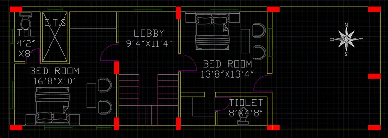
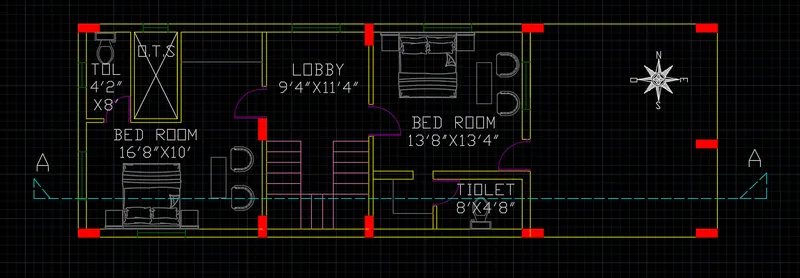
- CREATING OF FIRST FLOOR PLAN
- Select the wall layers from the layer properties
- Select a LINE from the ribbion for type L and press ENTER
- Draw a line and make a rectangle of length 60' and width as 20'
- Select the OFFSET from the ribbion or type O and press ENTER
- Specify the Offset distance as 9'' as the width of the outer wall
- Select the OFFSET from the ribbion or type O and press ENTER
- Click on THROUGH on the command line
- Specify the Offset distance for first room 16'8" in X DIRECTION and 10' in Y DIRECTION
- To create a wall give the offset of 9" for external wall and 4.5" for internal wall
- Repeat the same process
- Specify the Offset distance fort third room 4'2" in X DIRECTION and 8'2" in Y DIRECTION
- Specify the Offset distance for the fourth room 9'4" in X DIRECTION and 11'4' in Y DIRECTION
- Specify the Offset distance for fifth room 13'8" in X DIRECTION and 13'4" in Y DIRECTION
- Specify the Offset distance for the sixth room 8' in X DIRECTION and 4'8'' in Y DIRECTION
- Select the TRIM Ccommand from the ribbion and trim the unwanted lines.
- CREATE A DOOR OPENING
- Select a LINE tool or type L and press ENTER
- Specify a first point as a staring point of door and second point is throught the wall
- Select the OFFSET from the ribbion or type O and press ENTER
- specify the offset distance as size of door and select the last created line
- SIZES OF DOORS ARE -
- D -4' FOR MAIN ENTERNCE
- D1 - 3' ALL ROOM
- D2 - 2'6" FOR TOILET
- Select a WINDOWS LAYER
- Select a RECTANGLE tool or type a REC and press ENTER
- Click on DIMENSION in the command line
- Specify the length of rectangle and press enter
- Specif the width of rectangle and press enter
- Select a LINE tool or type L and press ENTER
- Create a line from th mid point of rectangle and trim the length of rectangle
- Select a COPY tool or type CO and press ENTER
- Specify a base point as mid point and place the window at the center of wall.
- SIZES OF WINDOW ARE -
- W = 4.5'
- V = 2'
- Select a COLUMN LAYER
- Select a RECTANGLE tool or type a REC and press ENTER
- Click on DIMENSION in the command line
- Specify the length of rectangle is 9"and press enter
- Specif the width of rectangle is 26" and press enter
- Now click on upper click of model space
- Select a HATCH from the ribbion
- Now select the hatch type is soild and click on by layer and slect a layer as column
- now press inside the rectangle
- Now select the rectangle and press it in desired location.
STEP 4
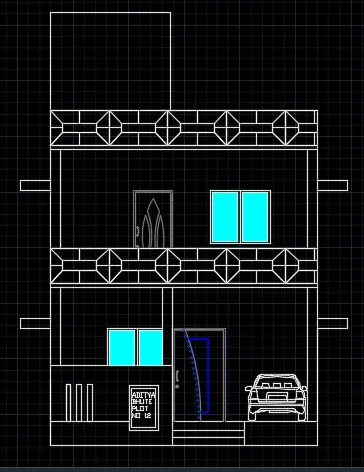
- CREATING THE ELEVATION
- Select a construction line by XL ENTER
- Take all thee references poits line column windows door from both the plan
- Now again select a xl line and click on horizontal in the command line and draww one horizontal line
- Select a offset tool from the ribbion or press o and press enter
- Specify the ofset distance as 1'10" as a plingth given to the house
- press esc
- Select a offset tool from the ribbion or press o and press enter
- Specify the ofset distance as 10' as a height of ground floor
- press esc
- Select a offset tool from the ribbion or press o and press enter
- Specify the ofset distance as 4" as a width of slab
- press esc
- Select a offset tool from the ribbion or press o and press enter
- Specify the ofset distance as 10' as a height of first floor
- press esc
- Select a offset tool from the ribbion or press o and press enter
- Specify the ofset distance as 4" as a slab width
- press esc
- Take a reference point of doors and windows from the plan by xl lines
- Select a LINE tool or type a L andd press ENTER
- and draw a window from 3' height aas sill level to the 7' height as lentel level
- and draw a door from a ground surface to the 7' height as a lentel level height is 7'
- Now draw a sunshade with the help of lines
- and top stair room of heigh 10'
STEP 5
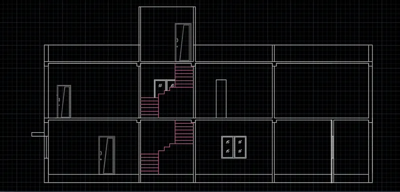
- CREATING THE SECTION
- To create the sectional elevation of the house we need to draw the section line
- First we draw the section line in ground level and name it as AA section
- Then draw the section line at hame distance from wall at first floor and name it as AA section
- Select a construction line by XL ENTER
- Take all thee references poits line column windows door from both the plan
- Now again select a xl line and click on horizontal in the command line and draww one horizontal line
- Select a offset tool from the ribbion or press o and press enter
- Specify the ofset distance as 1'10" as a plingth given to the house
- press esc
- Select a offset tool from the ribbion or press o and press enter
- Specify the ofset distance as 10' as a height of ground floor
- press esc
- Select a offset tool from the ribbion or press o and press enter
- Specify the ofset distance as 4" as a width of slab
- press esc
- Select a offset tool from the ribbion or press o and press enter
- Specify the ofset distance as 10' as a height of first floor
- press esc
- Select a offset tool from the ribbion or press o and press enter
- Specify the ofset distance as 4" as a slab width
- press esc
- Take a reference point of doors and windows from the plan by xl lines
- Select a LINE tool or type a L andd press ENTER
- and draw a window from 3' height aas sill level to the 7' height as lentel level
- and draw a door from a ground surface to the 7' height as a lentel level height is 7'
- Now draw a sunshade with the help of lines
- and top stair room of heigh 10'
STEP 6-
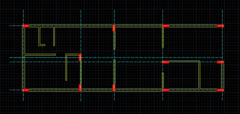
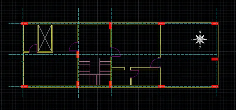
- CREATING A CENTER LINE PLAN
- Select a center line layer from the layer properties and turn off all the layer expect wall and column
- Let's first create the center line plan at ground level
- Select a LINE tool from the Ribbion or type L and press ENTER
- Now draw the line in between thw wall and extend it to some distance
- Now create the center line plan for first floor
- Select a LINE tool from the Ribbion or type L and press ENTER
- Now draw the line in between thw wall and extend it to some distance
STEP 7
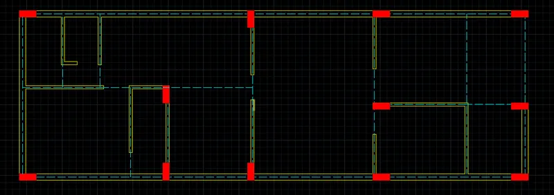
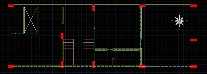
- CREATING A BEAM PLAN
- FOR GROUND FLOOR
- Select a Line tool from the ribbion or type L and press ENTER
- Now join all the column and create a line all all the wall to create a beam
- FOR FIRST FLOOR
- Select a Line tool from the ribbion or type L and press ENTER
- Now join all the column and create a line all all the wall to create a beam
STEP 8
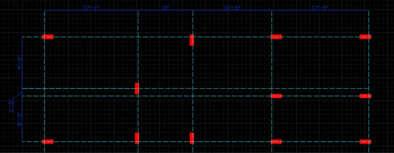
- COLUMN AND GRIDS
- Select a dimension layer from th layer properties and turn of wall the layer expect center line and column
- Now type DIMLIN for linera dimension
- specify the first point and second point and place the dimension
- Now type c for continue dimension and select the laster dimension and mark all the grid distance
STEP 9
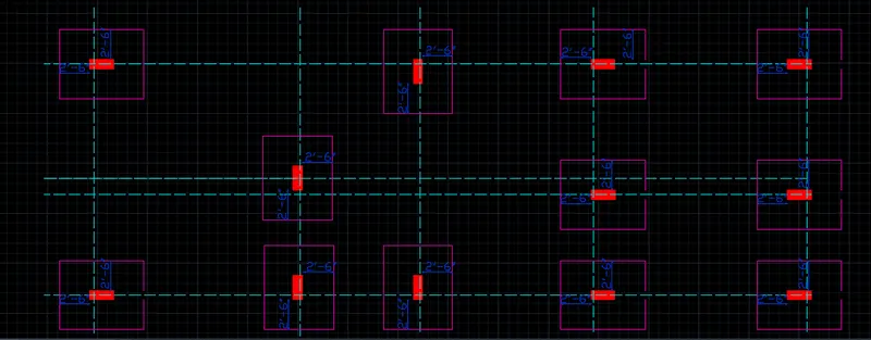
- CREATING OF FOOTING LAYOUT
- SELELCT A FOOTING LAYER from the layer propertis
- we have to create a footing of 7' x 5'9"
- So Select a OFFSET tool from the ribbion
- and specify the offset distance as 2'6" and select the column and give it outside of column
RESULT
1. ALL THE ARCHITECTURAL DRAWING
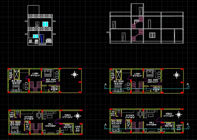
2. ALL THE STRUCTURAL DRAWING