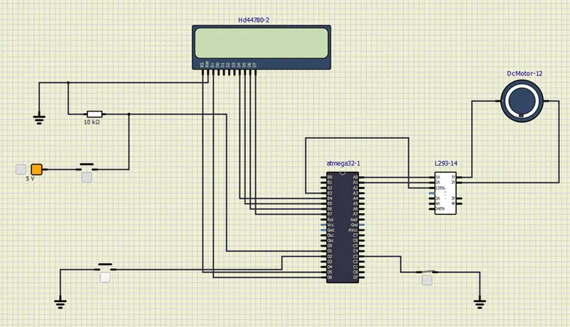
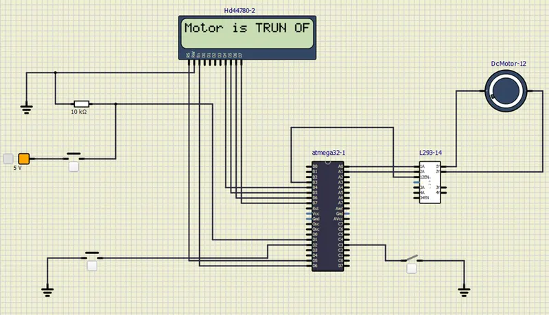
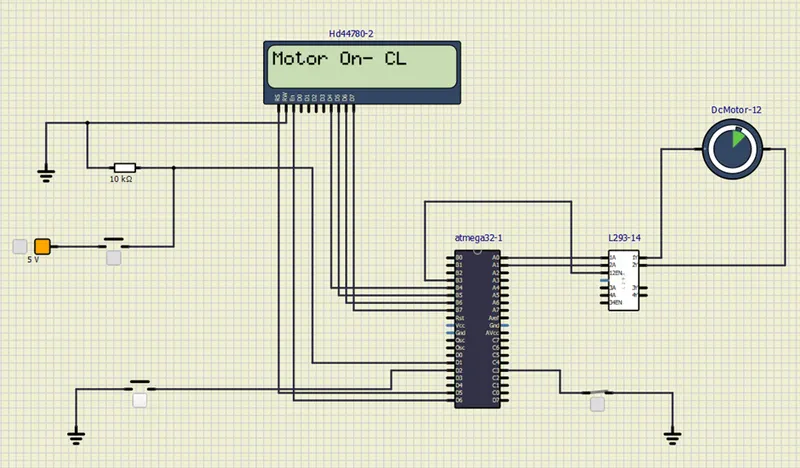
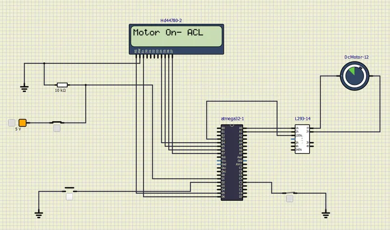
Project 1 - Controlling a DC motor using PWM and monitoring its Running status
Code for project:
#include <avr/io.h>// i/o registers of AVR
#define F_CPU 16000000L // define crystal frequency
#include "avr/interrupt.h" // extrnal intrrupt pin
#include <util/delay.h> // delay function purpose
#define sw_dir (PIND & (1<<1)) // d1 pin declared s push button
#define sw_dspd (PIND & (1<<2)) // d2 pin declared as push button
#define pw (PINC & (1<<3))// c3 declared as push button for power on/off
#define lcd_port PORTB // portb pins are for LCD data
#define RS_high PORTD |=(1<<5) //d5 pin used for register select
#define RS_low PORTD &=~(1<<5)//d5 pin is used for RS
#define EN_high PORTD |=(1<<6) //d6 used for unable
#define EN_low PORTD &=~(1<<6) //d6 used for unable
unsigned char i;
void lcd_cmd(char cmd)//command for LCD display
{
lcd_port=(cmd & 0xf0);// 4 bits for bit lcd mode
RS_low;
EN_low;
_delay_ms(1);//after 1ms disable lcd
EN_high;//enable the lcd
lcd_port=((cmd<<4)&(0xf0));//lcd port
RS_low;
EN_low;
_delay_ms(1);//after 1ms disable lcd
EN_high;
}
void lcd_data(char data)//send the data to lcd
{
lcd_port=(data & 0xf0);// 4 bit for 4 bit lcd mode
RS_high;
EN_low;
_delay_ms(1);
EN_high;
lcd_port=((data<<4)&(0xf0));//4 bit for 4 bit lcd mode
RS_high;
EN_low;
_delay_ms(1);
EN_high;
}
void lcd_init()
{
lcd_cmd(0x28);//used for 4 bit lcd mode
_delay_ms(5);
lcd_cmd(0x02);//return home
_delay_ms(5);
lcd_cmd(0x01);// clear screen
_delay_ms(5);
lcd_cmd(0x0C);//display on cursor off
_delay_ms(5);
lcd_cmd(0x06);//increment the display cursor
_delay_ms(5);
lcd_cmd(0x80);
_delay_ms(5);
}
void cursorpos(char x,char y)
{
if((x<1||x>2)||(y>16||y<1))//condition will check 2 rows and 16 columns
{
x=1;//x=row
y=1;//y=column
}
if(x==1)
{
lcd_cmd(0x7F+y);//for the 1st line hex decimal value (80)
}
else//(x=2)
{
lcd_cmd(0xBF+y);//{0C-1=0B} for starting the second line,2nd row
}
}
void lcd_out(char x,char y, char *str)
{
cursorpos(x,y);
while(*str)
{
lcd_data(*str);
str++;
}
}
int adc_read(char channel)//configuring adc value
{
unsigned int a,result;
ADMUX=channel;// select mux here using 2 bit
ADCSRA=0X80;//control and status register to enable the adc conversion
ADCH=0x00;//showing value0
ADCL=0x00;
ADCSRA |=(1<<6);//conversion become zero means conversion of adc(0x40 means inturrupt pin)
while((ADCSRA & 0x40)!=0);
a=ADCL; //dummy data type a and a is stored the ADCL register
result=ADCH;//store the high value
result=result<<8;
result=result |a;
return result;
}
int main(void)
{
DDRB = 0XFF;//declaring all 8 pins as output
DDRA |= ((1<<0)| (1<<1));//declaring A0 & A1 as output
DDRD &=~(1<<1); //declaring D1 pin as input
DDRD &=~(1<<2); //declaring d2 pin as input
DDRD |= (1<<5);//declaring d5 pin as output
DDRD |= (1<<6);//declaring d6 as output
DDRC &=~(1<<3);//declaring c3 pin as output
PORTD |= (1<<2);//enabling internal pull up register for d2
PORTC |= (1<<3);//enabling internal pull up register for d3
i=64;//initializing i=64 as we are running the motor with 25% duty cycle
TCCR0 = 0X61;// non inverting mode PWN phase correct mode
GICR = (1<<INT0);//using INT0 for interrupt
MCUCR = 0X02;
sei();//unable global interrupt
lcd_init();//initialize lcd
while(1)
{
while(pw==0)//continue till push button released
{
if(sw_dir==0)// direction control push button released
{
PORTA = 0b00000001; //10 to respective 1A 2A pins to rotate in clockwise direction
lcd_out(1,1,"Motor On-CL");//running clockwise direction
}
else
{
PORTA = 0b00000010;
lcd_out(1,1,"Motor On-ACL");
}
OCR0 = i; //i increses in ISR
}
PORTA = 0x00;
lcd_out(1,1,"Motor is TURN OFF");
}
}
ISR(INT0_vect)//interrupt service routine
{
i=i+20;
}
Output: