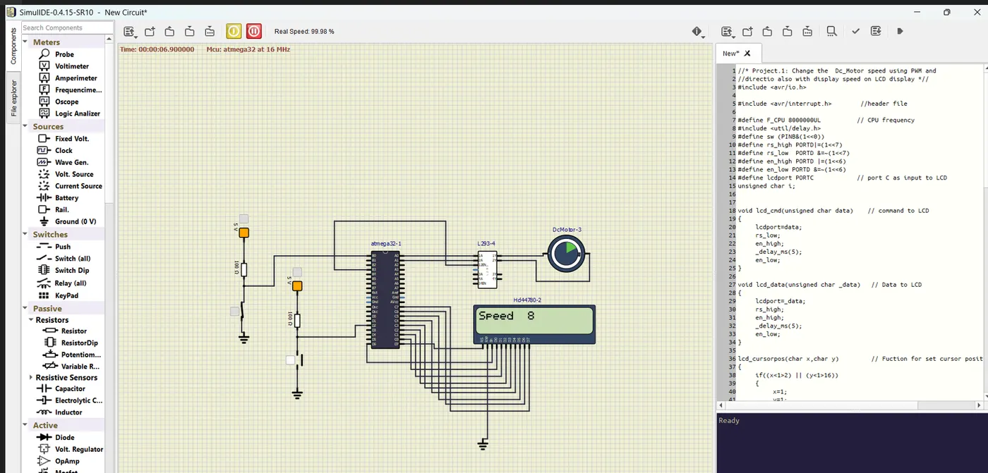
Project 1 - Controlling a DC motor using PWM and monitoring its Running status
Project 1 - Controlling a DC motor using PWM and monitoring its Running status
Implement a system on the simulator for controlling a DC motor using L293 motor driver, monitor its status and print the running status of motor on the LCD Display.
Goal:
Implement a system on simulator for Controlling the DC motor using L293 motor driver.
Displaying the running status of DC motor on the LCD display.
Key Highlights of the Project:
The DC motor can be controlled by using L293 motor driver.
The speed of a DC motor can be controlled by varying its input voltage, for doing this is to use PWM (Pulse Width Modulation).
L293D IC is a typical Motor Driver IC which allows the DC motor to drive on any direction.
Deliverables of this project:
Implement the system for controlling DC motor.
Controlling the speed of the DC motor using PMW.
Displaying the present running status of DC machine on LCD display.
Expected Outcomes:
Implement a system on simulator to control a DC motor using PMW
Monitoring the running status of the DC motor using L293 motor driver which allows the DC motor to drive on any direction.
Running status i.e. on which direction the DC motor is running is to be displayed on the LCD screen.
SOLUTION
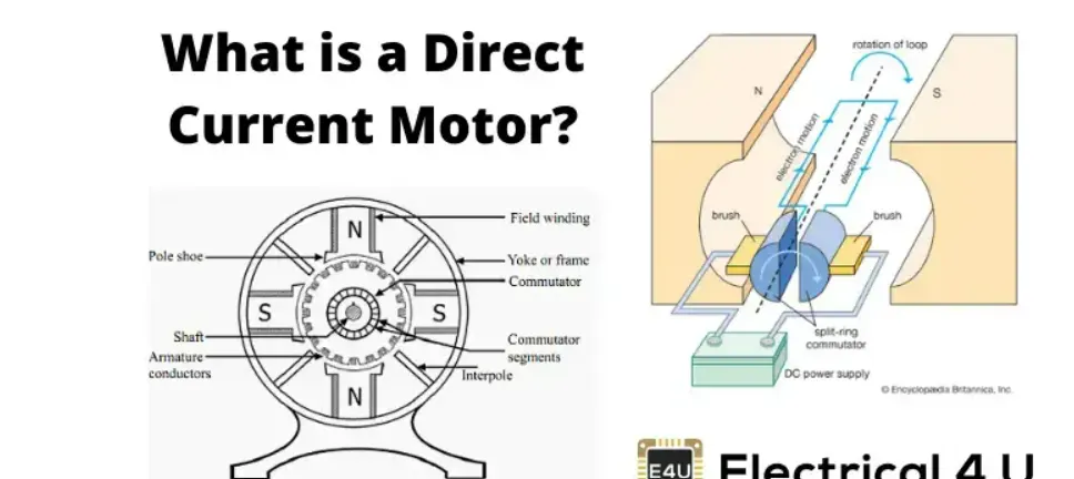
DC MOTOR
A DC motor is defined as a class of electrical motors that convert direct current electrical energy into mechanical energy.
When kept in a magnetic field, a current-carrying conductor gains torque and develops a tendency to move.
Thus when electric fields and magnetic fields interact, a mechanical force arises.
This is the principle on which the DC motors work.
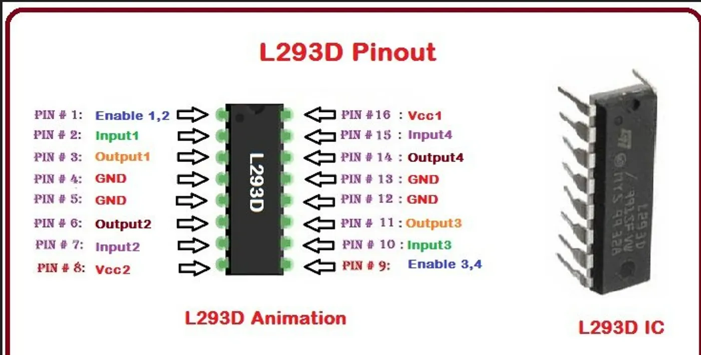
L293 Motor Driver:
L293d IC is known as a motor driver.
It is a low voltage operating device like other ICs.
The other ICs could have the same functions like L293d but they cannot provide the high voltage to the motor.
CODE
#include <avr/io.h> // includes necessary header files //
#include <util/delay.h> // includes necessary header files. //
#include <avr/interrupt.h> // includes necessary header files.//
#define F_CPU 8000000UL //Defines the CPU frequency as 8 MHz.//
#define sw (PINB&(1<<0))
#define rs_high PORTD|=(1<<7)
#define rs_low PORTD &=~(1<<7)
#define en_high PORTD |=(1<<6)
#define en_low PORTD &=~(1<<6)
#define lcdport PORTC //port C as input to LCD//
unsigned char i;
void lcd_cmd(unsigned char data) //sends a command to the LCD display.//
{
lcdport = data;
rs_low;
en_high; // enable the LCD
_delay_ms(5); //after 5ms disable LCD
en_low;
}
void lcd_data(unsigned char _data) // sends data to the LCD display.//
{
lcdport = _data;
rs_high; //access data register
en_high;
_delay_ms(5);
en_low;
}
void lcd_cursorpos(char x, char y) //sets the cursor position on the LCD.//
{
if ((x < 1 || x > 2) || (y < 1 || y > 16)) //condition will check the rows and 16 columns
{
x = 1;
y = 1;
}
if (x == 1) {
lcd_cmd(0x7F + y);
} else {
lcd_cmd(80xBF + y);
}
}
void lcd_print(char x, char y, char *str) // prints a string on the LCD at a specified position.//
{
lcd_cursorpos(x, y);
while (*str) {
lcd_data(*str);
str++;
}
}
void lcd_init() // initializes the LCD for operation.//
{
lcd_cmd(0x38);
_delay_ms(5);
lcd_cmd(0x02);
_delay_ms(5);
lcd_cmd(0x01);
_delay_ms(5);
lcd_cmd(0x0C);
_delay_ms(5);
lcd_cmd(0x06);
_delay_ms(5);
lcd_cmd(0x80);
_delay_ms(5);
}
int main(void) // port configuration//
{
DDRB |= (1 << 0); //Configures Pin 0 of Port B as an output.//
PORTB |= (1 << 0); // Sets Pin 0 of Port B to high (initializes it to 1).//
DDRA = (1 << 0); //Configures Pin 0 of Port A as an output.//
DDRA = (1<<1); //Configures Pin 1 of Port A as an output.//
DDRD &= ~(1 << 2);
PORTD |= (1 << 2); //Enables the internal pull-up resistor on Pin 2 of Port D.//
DDRB |= (1 << 3); //Configures Pin 3 of Port B as an output.//
PORTC = 0xFF;
lcd_init();
lcd_print(1, 1, "Speed ");
TCCR0 = 0x64; // Configures Timer 0 for controlling the motor speed.//
i = 64; // Initializes the variable i with the value 64.//
OCR0 = i; //Sets the Output Compare Register for Timer 0 to the initial value of i.//
GICR |= (1 << INT0); // Enables external interrupts globally.//
MCUCR = 0x02; // Configures the external interrupt on the falling edge of INT0.//
char buffer[10];
sei();
while (1) // An infinite loop where the main program logic resides.//
{
if (sw == 0) // Checks the state of the switch (sw) and adjusts the motor direction accordingly.//
{
PORTA |= (1 << 1);
PORTA &= ~(1 << 0);
} else {
PORTA |= (1 << 0);
PORTA &= ~(1 << 1);
}
OCR0 = i;
lcd_print(1, 8, " ");
lcd_print(1, 8, itoa(i, buffer, 10));
;}
return 0;}
ISR(INT0_vect) // This is an interrupt service routine triggered by an external interrupt (INT0). //
{
i+=25;
}
CIRCUIT