Project 1 - Controlling a DC motor using PWM and monitoring its Running status
Ans:-
Overview of the Project:
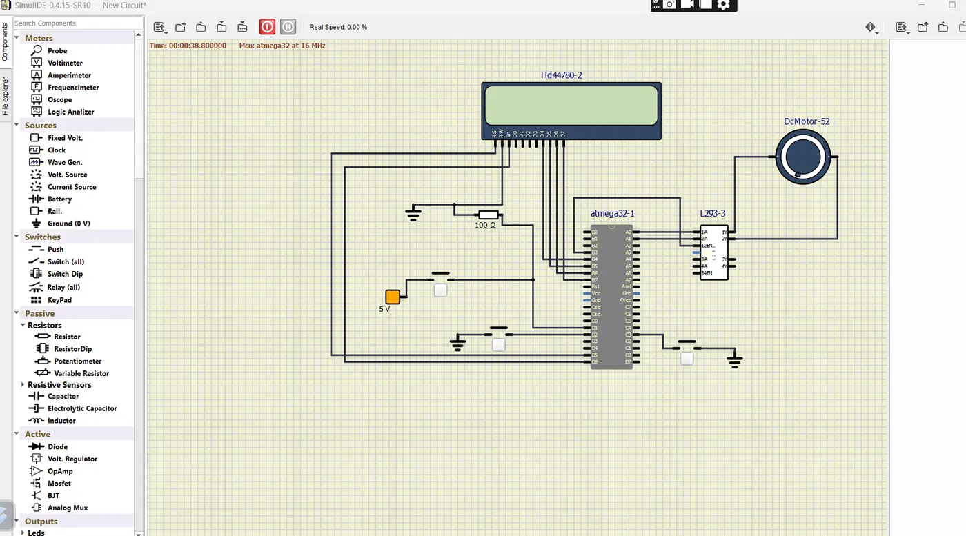
Implement a system on the simulator for controlling a DC motor using L293 motor driver, monitor its status and print the running status of motor on the LCD Display.
Goals:
- Implement a system on simulator for Controlling the DC motor using L293 motor driver.
- Displaying the running status of DC motor on the LCD display.
Key Highlights of the Project:
- The DC motor can be controlled by using L293 motor driver.
- The speed of a DC motor can be controlled by varying its input voltage, for doing this is to use PWM (Pulse Width Modulation).
- L293D IC is a typical Motor Driver IC which allows the DC motor to drive on any direction.
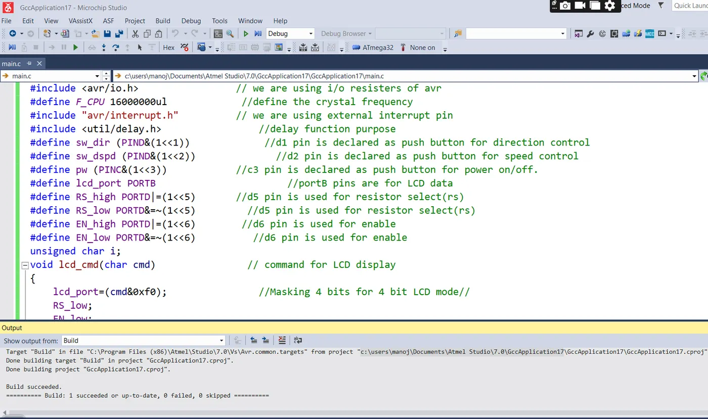
CODE-
#include <avr/io.h> // we are using i/o resisters of avr
#define F_CPU 16000000ul //define the crystal frequency
#include "avr/interrupt.h" // we are using external interrupt pin
#include <util/delay.h> //delay function purpose
#define sw_dir (PIND&(1<<1)) //d1 pin is declared as push button for direction control
#define sw_dspd (PIND&(1<<2)) //d2 pin is declared as push button for speed control
#define pw (PINC&(1<<3)) //c3 pin is declared as push button for power on/off.
#define lcd_port PORTB //portB pins are for LCD data
#define RS_high PORTD|=(1<<5) //d5 pin is used for resistor select(rs)
#define RS_low PORTD&=~(1<<5) //d5 pin is used for resistor select(rs)
#define EN_high PORTD|=(1<<6) //d6 pin is used for enable
#define EN_low PORTD&=~(1<<6) //d6 pin is used for enable
unsigned char i;
void lcd_cmd(char cmd) // command for LCD display
{
lcd_port=(cmd&0xf0); //Masking 4 bits for 4 bit LCD mode//
RS_low;
EN_low;
_delay_ms(1); //after 1ms disable LCD
EN_high; // enable the LCD
lcd_port=((cmd<<4)&(0xf0)); // LCD port
RS_low;
EN_low;
_delay_ms(1); //after 1ms disable LCD
EN_high; // enable the LCD
}
void lcd_data(char data) //send the data to LCD
{
lcd_port=(data &0xf0); //masking 4 bits for bit LCD mode//
RS_high; //access data register
EN_low;
_delay_ms(1);
EN_high;
lcd_port=((data<<4)&(0xf0)); //masking 4 bits for bit LCD mode//
RS_high; //access data register
EN_low;
_delay_ms(1);
EN_high;
}
void lcd_init()
{
lcd_cmd(0x28);
_delay_ms(5); //used for 4 bits LCD mode //
lcd_cmd(0x02);
_delay_ms(5); //return the cursor to home//
lcd_cmd(0x01);
_delay_ms(5); //clear screen //
lcd_cmd(0x0C);
_delay_ms(5); //display ON cursor OFF//
lcd_cmd(0x06);
_delay_ms(5); //increment cursor//
lcd_cmd(0x80);
_delay_ms(5); //force cursor to begin 1st line //
}
void cursorpos(char x, char y)
{
if ((x<1||x>2)||(y>16)||(y<1)) //condition will check the rows and 16 columns
{
x=1; //x=rows
y=1; //y=columns
}
if (x==1)
{
lcd_cmd(0x7F+y); //{80-1=0B}for starting the first list hex decimal value(80){y we are the 7F+y means we need to start from that column
}
else //(x=2)
{
lcd_cmd(0xBF+y); //{0C-1=0B} for starting the second line, 2nd row
}
}
void lcd_out(char x, char y, char *str) //here we are checking which position we want to print
{
cursorpos(x,y);
while (*str)
{
lcd_data(*str);
str++;
}
}
int adc_read(char channel) // we are configuring the adc value
{
unsigned int a, result;
ADMUX=channel; //here we are going to use which channel we need to select in mux here using 2 bit
ADCSRA=0X80; // control and status register to enable the adc conversion enable the interrupt flag adc interrupt ADEN=1
ADCH=0x00; // showing the value 0 or clearing the adc register
ADCL=0x00; //showing the value 0
ADCSRA|=(1<<6); // to start the conversion 6 bit adsc high
while((ADCSRA&0x40)!=0); // when the conversion become zero means conversion of adc (0x40means interrupt pin)
a=ADCL; //dummy data type a and ais stored the adcl register (ADC0-ADC7)
result=ADCH; //store the high value (ADC8-ADC9)
result=result<<8; //to get proper result or aligned value we need to do left shift
result=result|a; //we are adding the ADCL+ADCH to get 16 bits
return result;
}
int main(void)
{
DDRB=0xFF; // declaring all 8 pins as output
DDRA|=((1<<0)|(1<<1)); // declaring A0 and A1 as output
DDRD&=~(1<<1); //declaring D1 pin as input
DDRD&=~(1<<2); //declaring D2 pin as input
DDRD|=(1<<5); //declaring D5 pin as output
DDRD|=(1<<6); //declaring D6 pin as output
DDRC&=~(1<<3); //declaring C3 pin as input
PORTD|=(1<<2); //enabling internal pull up resistor for D2
PORTC|=(1<<3); //enabling internal pull up resistor for D3
i=64; // initializing i=64 because we are running the motor with 25%duty cycle
TCCR0=0X61; // non inverting mode, PWM phase correct mode, no pre scalar
GICR=(1<<INT0); // using into for interrupt
MCUCR=0X02; // make interrupt negative edge triggered
sei(); //enable global interrupt
lcd_init(); // initialized LCD
while (1)
{
while(pw==0) //continue till push button is released
{
if (sw_dir==0) // if the direction control push button is released
{
PORTA=0b00000001; //10 respective 1A 2A pins to rotate in clockwise direction
lcd_out(1,1,"Motor ON-CLW"); // running clockwise direction
}
else
{
PORTA=0b00000010; //10 respective 1A 2A pins to rotate in anti-clockwise direction
lcd_out(1,1,"Motor ON-ACL"); // running anti-clockwise direction
}
OCR0=i; // i increase in ISR, the corresponding value is to be loaded into OCR0
}
PORTA=0X00; //0 0 to respective 1A 2A pins to stop condition
lcd_out(1,1,"Motor is_OFF");
}
}
ISR(INT0_vect) // interrupt service routine
{
i=i+20; //as i increases the duty cycle also increases .i increases by 20 in each push and the corresponding value is to be loaded into OCR0 in while loop
}
Normal circuit Diagram
Expected Outcomes:
- Implement a system on simulator to control a DC motor using PMW
- Monitoring the running status of the DC motor using L293 motor driver which allows the DC motor to drive on any direction.
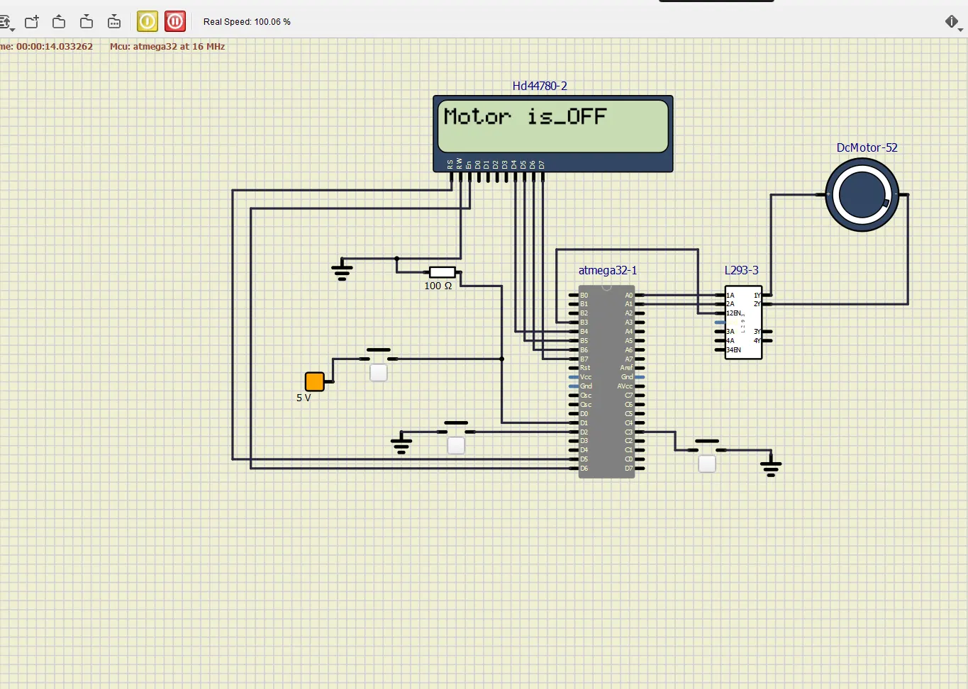
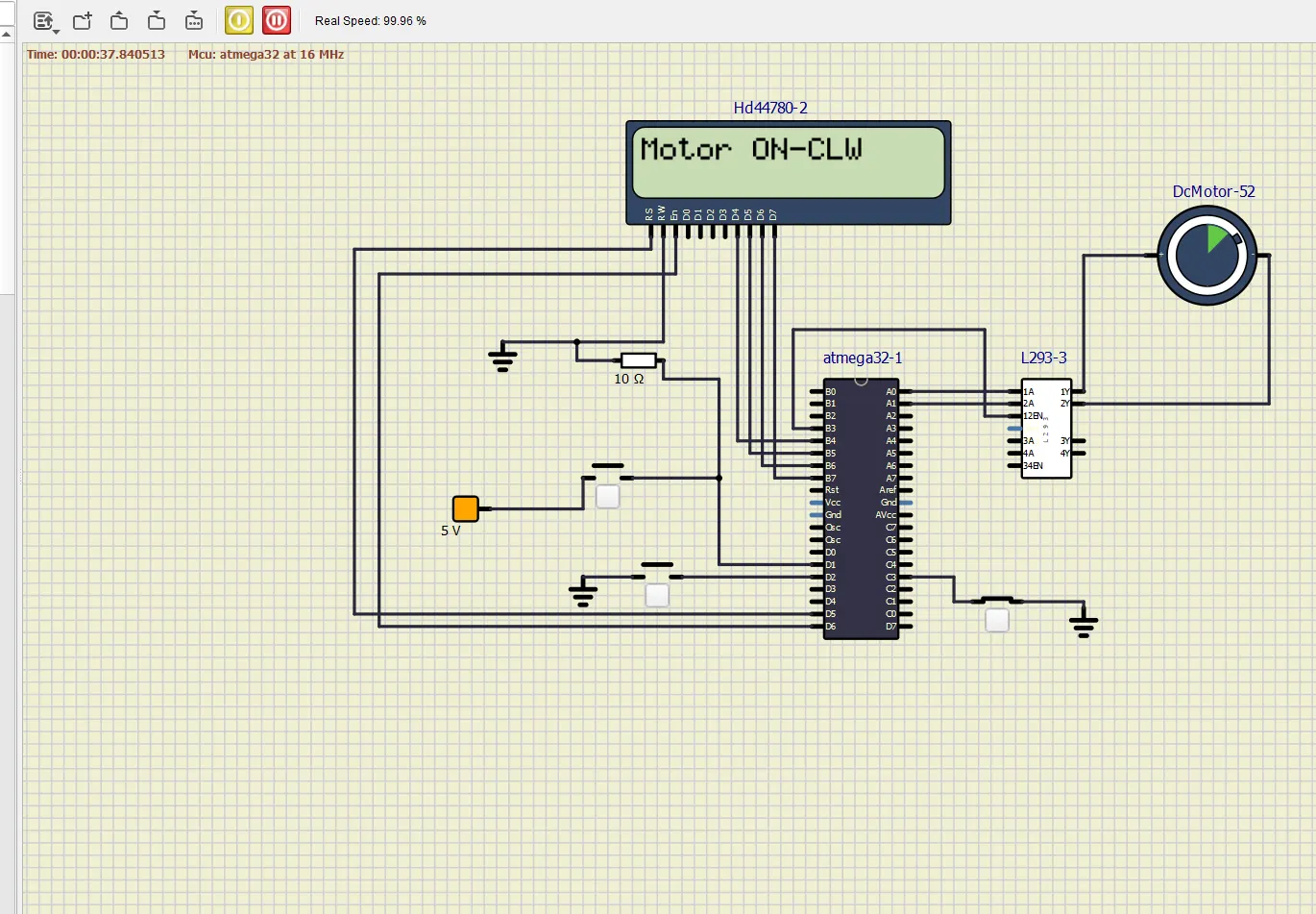
- Running status i.e. on which direction the DC motor is running is to be displayed on the LCD screen.
When Motor is off
Motor Rotating clock wise direction
Motor Rotating Anti clock wise direction
