Aim:
To implement a system on the simulator for controlling a DC motor using L293 motor driver, monitor its status and print the running status of motor on the LCD Display.
Objective:
- Implement a system on simulator for Controlling the DC motor using L293 motor driver.
- Displaying the running status of DC motor on the LCD display.
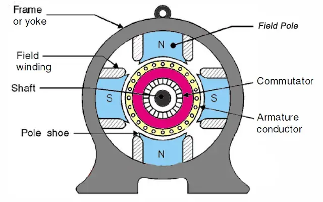
- DC motors are widely used in industrial projects for their robustness and control. They offer precise speed and torque control, making them suitable for various applications, such as conveyor systems, robotics, and machinery. These motors are known for their reliability and ability to maintain consistent performance in demanding environments. Industrial DC motors can be powered by a direct current power supply and are often equipped with feedback mechanisms like encoders for accurate position and speed control. They play a critical role in automating and enhancing the efficiency of industrial processes, contributing to increased productivity and reduced downtime.
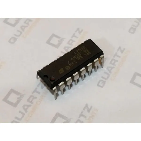
The L293D motor driver is a popular integrated circuit used to control DC motors and stepper motors. Three key points about the L293D motor driver are:
-
Dual H-Bridge Configuration: The L293D features two H-bridge circuits, allowing it to control the direction and speed of two DC motors independently. This flexibility is essential for applications like robotics and vehicles.
-
Built-In Diodes: L293D has built-in flyback diodes, which are essential for protecting the driver and connected microcontrollers from voltage spikes generated by the motors. This feature simplifies the circuit design.
-
Compatibility: L293D is compatible with a wide range of microcontrollers and logic devices, making it a versatile choice for motor control in various projects. It is commonly used in Arduino and Raspberry Pi projects.
These features make the L293D motor driver a popular choice for motor control in hobbyist and small-scale industrial applications.
\
code :CPP
// Include the LiquidCrystal library
#include

// Initialize the LCD object with pin numbers for RS, E, D4, D5, D6, and D7
LiquidCrystal lcd(12, 11, 5, 4, 3, 2);

// Define pin assignments for components
#define potentiometer A0  // Connect the potentiometer to analog pin A0
#define bt_F A1          // Connect the Forward button to analog pin A1
#define bt_S A2          // Connect the Stop button to analog pin A2
#define bt_B A3          // Connect the Backward button to analog pin A3
#define M1_34EN 10       // Connect the motor's 3, 4 EN pin to digital pin 10
#define M1_3A 9          // Connect the motor's 3A pin to digital pin 9
#define M1_4A 8          // Connect the motor's 4A pin to digital pin 8

int read_ADC = 0;         // Variable to store the potentiometer reading
int duty_cycle;           // Calculated duty cycle
int duty_cycle_lcd;       // Duty cycle value for display
int set = 0;              // Variable to store the motor direction setting

void setup() {
  // Initialize serial communication for debugging
  Serial.begin(9600);

  // Set the pinMode for input and enable pull-up resistors for buttons
  pinMode(potentiometer, INPUT);
  pinMode(bt_F, INPUT_PULLUP);
  pinMode(bt_S, INPUT_PULLUP);
  pinMode(bt_B, INPUT_PULLUP);

  // Set the pinMode for motor control pins
  pinMode(M1_34EN, OUTPUT);
  pinMode(M1_3A, OUTPUT);
  pinMode(M1_4A, OUTPUT);

  // Initialize the LCD with 16 columns and 2 rows
  lcd.begin(16, 2);

  // Display a greeting message
  lcd.setCursor(0, 1);
  lcd.print("Hi");
  delay(2000);
  lcd.clear();  // Clear the LCD
}

void loop() {
  // Read the potentiometer's analog value
  read_ADC = analogRead(potentiometer);

  // Map the analog value to a duty cycle between 0 and 255
  duty_cycle = map(read_ADC, 0, 1023, 0, 255);

  // Map the duty cycle to a percentage value (0-100)
  duty_cycle_lcd = map(read_ADC, 0, 1023, 0, 100);

  // Set the motor's PWM duty cycle
  analogWrite(M1_34EN, duty_cycle);

  // Display the duty cycle on the LCD
  lcd.setCursor(0, 0);
  lcd.print("Duty Cycle:");
  lcd.print(duty_cycle_lcd);
  lcd.print("%  ");

  // Check button presses and set the motor direction
  if (digitalRead(bt_F) == 0) {
    set = 1;
  }
  if (digitalRead(bt_S) == 0) {
    set = 0;
  }
  if (digitalRead(bt_B) == 0) {
    set = 2;
  }

  // Update the LCD based on the motor direction
  lcd.setCursor(0, 1);
  if (set == 0) {
    lcd.print("   Stop   ");
    digitalWrite(M1_3A, LOW);
    digitalWrite(M1_4A, LOW);
  }
  if (set == 1) {
    lcd.print("   Clockwise   ");
    digitalWrite(M1_3A, HIGH);
    digitalWrite(M1_4A, LOW);
  }
  if (set == 2) {
    lcd.print("   Anticlockwise   ");
    digitalWrite(M1_3A, LOW);
    digitalWrite(M1_4A, HIGH);
  }

  delay(50);  // Small delay for button stability
}