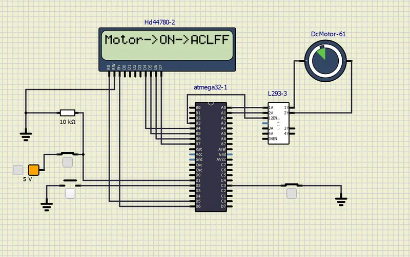
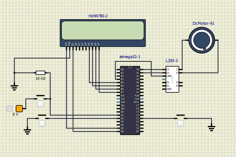
General Instructions:-
In this circuit totally there are three push buttons are there,
• The button which is connect in port C as C3 is power
• the button which is connect in port D as D2 is speed control by duty cycle and also
known as interrupt push button.
• the button which is connect in port D as D1 is direction control.
Interrupts Pins for ATmega-32
D2 is for INT0
D3 is for INT1
L293 MOTOR DRIVER
• L293d Integrated Circuit is known as a motor driver.
• Motor driver is used to control motion of a motor and its direction.
• The L293D is capable of bidirectional drive currents of up to 600 mA.
• Low voltage device
• Wide Supply-Voltage Range: 4.5 V to 36.
• Configure the direction of the motor
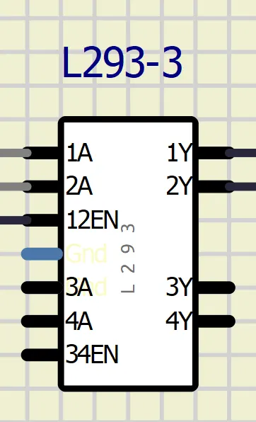
• The 1A and 2A are direction of rotation of the motor
• the 1Y and 2Y are connected to terminals of the DC motor
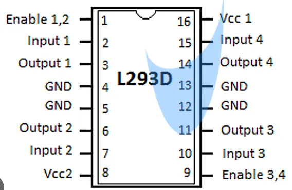
Pin diagram :
COMPONENTS:
• AT mega 32
• 3 push buttons
• 2xLCD (hd44780-166)
• DC moto 12v
• voltage source
• 10K resistor
• L293 motor driver
Working principle:
The principle of this project is to controlling the DC motor with three methods such as speed control, direction control and ON/OFF control switch.Totally there are three push button are connected in the circuit. If we ON the motor switch means the DC motor will rotate in clock wise direction then if we ON the motor switch and direction switch means the motor will rotate in anti clock wise direction. In the two cases the direction switch will be ON only.
HEADER FILES:
#include <avr/io.h> // input and output register of avr
#define F_CPU 16000000L // (CPU) crystal frequency
#include "avr/interrupt.h" // external interrupt pin
#include <util/delay.h> // delay function
#define sw_dir (PIND&(1<<1)) // push button for direction control d1
#define sw_spd (PIND&(1<<2)) // push button for speed control d2
#define pw (PINC & (1<<3)) // push button for power ON/OFF of C3
#define lcdport PORTB // data lines named as lcdport
#define rs_high PORTD|=(1<<5); // register selector high by setting
#define rs_low PORTD &= ~(1<<5); // register selector low by clearing
#define en_high PORTD|=(1<<6); // enable high by setting
#define en_low PORTD &= ~(1<<6); // enable low by clearing
PROGRAM:
#include <avr/io.h> //input and output register of avr
#define F_CPU 16000000L // cpu crystal frequency
#include "avr/interrupt.h" // external interrupt pin
#include <util/delay.h> // delay function
#define sw_dir (PIND & (1<<1)) // push button for direction control d1
#define sw_dspd (PIND & (1<<2)) // push button for speed control d2
#define pw (PINC & (1<<3)) // push button for power ON/OFF of C3
#define lcd_port PORTB //PORTB pins are for LCD data
#define rs_high PORTD |= (1<<5) // register selector high by setting
#define rs_low PORTD &=~ (1<<5) // register selector low by clearing
#define en_high PORTD |= (1<<6) // enable high by setting
#define en_low PORTD &=~ (1<<6) // enable low by clearing
unsigned char i;
void lcd_cmd(char cmd) //LCD command function
{
lcd_port = (cmd & 0xf0); //4 bits for 4 bit LCD mode
rs_low;
en_low;
_delay_ms(1); //after 1ms disable LCD
en_high; //enable the LCD
lcd_port = ((cmd<<4) & (0xf0)); //LCD port
rs_low;
en_low; // ENABLE LOW
_delay_ms(1); //after 1ms disable LCD
en_high; //enable the LCD
}
void lcd_data (char data) //send the data to lcd
{
lcd_port = (data & 0xf0); //4 bits for 4 bit lcd mode
rs_high; //access data register
en_low;
_delay_ms(1); //after 1ms disable LCD
en_high;
lcd_port = ((data<<4) & (0xf0)); //4 bits for 4 bit lcd mode
rs_high; //access data register
en_low;
_delay_ms(1); //after 1ms disable LCD
en_high;
}
void lcd_init() // LCD initialization function
{
lcd_cmd(0x28);// used for 4 bit lcd mode , 2 lines and 5x7 matrix
_delay_ms(5);
lcd_cmd(0x02); // return home
_delay_ms(5);
lcd_cmd(0x01); // clear screen
_delay_ms(5);
lcd_cmd(0x0C); // display on cursor off
_delay_ms(5);
lcd_cmd(0x06); // increment the display cursor
_delay_ms(5);
lcd_cmd(0x80); // force cursor to begin from 1st line
_delay_ms(5);
}
void cursorpos(char x,char y) // THIS FUNCTION IS TO PRINT ANY VALUE TILL DESIRED DIGIT IN LCD
{
if((x<1 || x>2) || (y>16 || y<1 )) // 2 rows and 16 columns in LCD display
{
x=1; //x == row
y=1; //y == column
}
if(x==1)
{
lcd_cmd(0x7F + y); // { 80-1 = 7F}-->starting 1st line hex decimal value (80) and cursor force begin first line in LCD display.
}
else //(x==2)
{
lcd_cmd(0xBF + y); //{0C-1 = 0B}-->> starting t 2nd line, 2nd row in LCD display.
}
}
void lcd_out(char x, char y, char *str) //*str- character strin
{
cursorpos(x,y); // function calling
while(*str) // super loop
{
lcd_data(*str);
str++; //increment loop
}
}
int adc_read(char channel) // adc read function with character as input
{
unsigned int a, result;
ADCSRA = 0X80; //adc control & status register to enable the adc conversion.
ADMUX = channel; // adc channel and select which channel need to select mux
ADCL = 0x00; // ADC register to hold lower byte with zero
ADCH = 0X00; // holds higher byte with value of zero
ADCSRA |= (1<<6); // enable the ADC start conversion bit with 6th bit
while((ADCSRA & 0x40) != 0); // conversion become zero means conversion of adc
a= ADCL; // store lower byte data with dummy data type a
result = ADCH; // store higher byte data
result = result<<8; // left shifting to get proper result
result = result | a ; // both ADCL and ADCH combined together
return result;
}
int main(void) // Main function of the program
{
DDRB = 0XFF; //set the portB as lcdport output and all 8-pins as output.
DDRA |= ((1<<0)| (1<<1)); //Declaring A0, A1 pins as output.
DDRD &=~ (1<<1); // D1 pin as input.
DDRD &=~ (1<<2); // D2 pin as input.
DDRD |= (1<<5); // D5 pin as output.
DDRD |= (1<<6); // D6 pin as output.
DDRC &=~ (1<<3); // C3 pin as input.
PORTD |= (1<<2); //enabling internal pull up resistor for D2.
PORTC |= (1<<3); //enabling internal pull up resistor for D3.
i=64; //initializing i=64 for running the motor with 25% duty cycle.
TCCR0=0X61; //Non-Inverting mode and PWM phase correct mode thn NO pr scalar.
GICR=(1<<INT0); // using INT0 for interrupt
MCUCR=0X02; //make interrupt negative edge triggered
sei(); //Enable global interrupt
lcd_init(); //Initialize lcd function
while (1) // super loop
{
while(pw == 0) //display till push button is released.
{
if(sw_dir == 0) //if the direction control push button is released.
{
PORTA = 0b00000001; // 1 0 to respective 1A 2A pins to rotate in clockwise direction of the motor in L293-3.
lcd_out(1,1,"MOTOR->ON->CLK"); //Running clock wise direction and displays in lcd
}
else
{
PORTA = 0b00000010; // 1 0 to respective 1A 2A pins to rotate in Anti-Clockwise direction in L293-3.
lcd_out(1,1,"Motor->ON->ACL"); //Running anti clock wise direction and displays in lcd
}
OCR0 = i; //i increases interrupt service routine the corresponding value to loaded into OCR0.
}
PORTA = 0x00; // 0 0 to respective 1A 2A pins to Stop rotation.
lcd_out(1,1,"Motor--->TURNOFF"); // motor is turn off mode
}
}
ISR(INT0_vect) // interrupt service routine
{
i=i+20; // if i increases the duty cycle also increases. i increases by 20 in each push
}
OUTPUT
THERE IS NO POWER SUPPLY IN CIRCIUT CONNECTION.
THERE IS POWER SUPPLY TO CIRCUIT BUT MOTOR IS TURN OFF.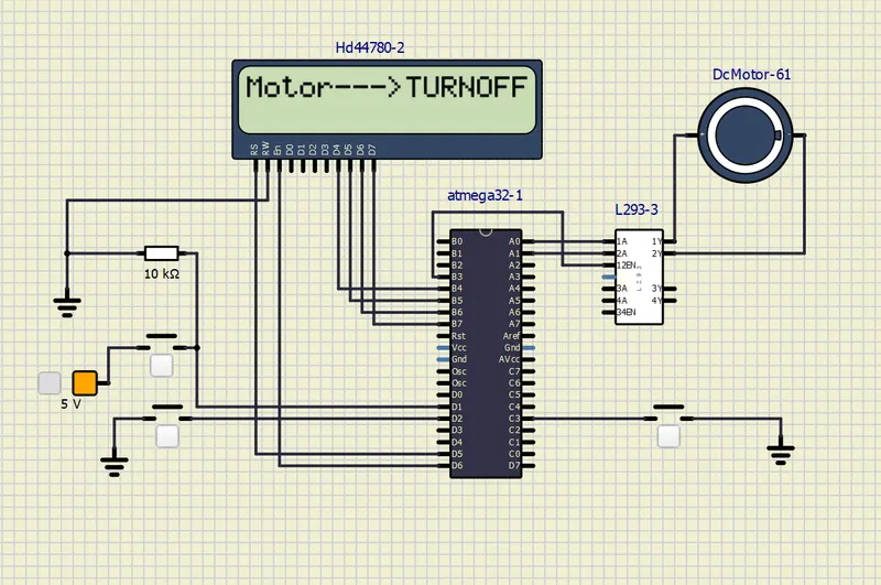
THE MOTOR IS CLOCK WISE DIRECTION WHEN PUSH BUTTON IS ON
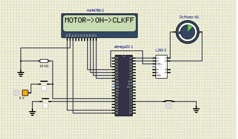
THE MOTOR IS ANTI CLOCK WISE DIRECTION WHEN BOTH PUSH BUTTON IS ON