Project 1 - Controlling a DC motor using PWM and monitoring its Running status
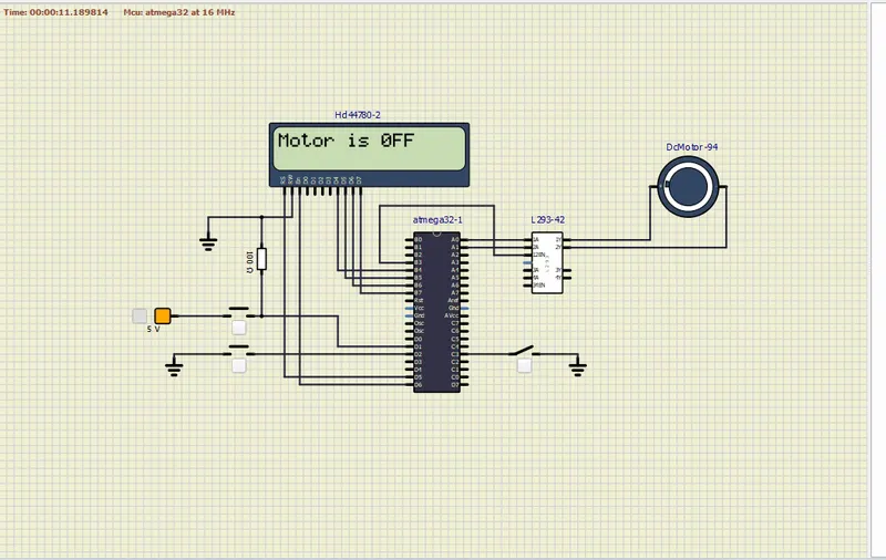
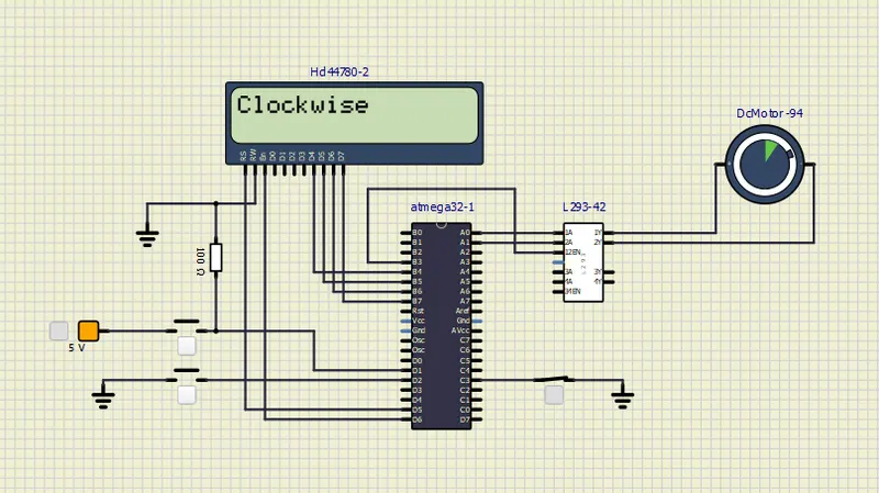
Implement a system on the simulator for controlling a DC motor using L293 motor driver, monitor its status and print the running status of motor on the LCD Display.
#include <avr/io.h>
#define F_CPU 16000000L
#include <util/delay.h>
#include "avr/interrupt.h"
#define lcd_port PORTB
#define RS_high PORTD |= (1<<5)
#define RS_low PORTD &= ~(1<<5)
#define EN_high PORTD |= (1<<6)
#define EN_low PORTD &= ~(1<<6)

#define sw_dir (PIND & (1<<1)) // d1 pin push button for direction control.
#define sw_dspd (PIND & (1<<2)) // d2 as push button for speed control.
#define pw (PINC & (1<<3)) // c3 as push button for power ON/OFF

unsigned char i=50;

void lcd_cmd(unsigned char cmd)
{
	lcd_port = (cmd & 0xf0);
	RS_low;
	EN_low;
	_delay_ms(1); //after 1ms disable LCD
	EN_high;
	lcd_port = ((cmd<<4) & (0xf0)); // LCD port
	RS_low;
	EN_low;
	_delay_ms(1); //after 1ms disable LCD
	EN_high; // enable the LCD

}

void lcd_data(unsigned char data)
{
	lcd_port = (data & 0xf0);
	RS_high; //access data register
	EN_low;
	_delay_ms(1);
	EN_high;
	lcd_port = ((data<<4) & (0xf0));
	RS_high; //access data register
	EN_low;
	_delay_ms(1);
	EN_high;
}

void lcd_init()
{
	lcd_cmd(0X28);
	_delay_ms(10);
	lcd_cmd(0X38);
	_delay_ms(10);
	lcd_cmd(0X02);
	_delay_ms(10);
	lcd_cmd(0X01);
	_delay_ms(10);
	lcd_cmd(0X0C);
	_delay_ms(10);
	lcd_cmd(0X06);
	_delay_ms(10);
	lcd_cmd(0X80);  // R0 C0
	_delay_ms(10);
}

void cursor_pos(char x, char y)
{
	if((x<1||x>2)||(y<1||y>16))
	{
		x=1;
		y=1;
	}
	if(x==1)
	{
		lcd_cmd(0X7F+y);
	}
	else if(x==2)
	{
		lcd_cmd(0XBF+y);
	}
}


void lcd_out(char x, char y, char *str)
{
	cursor_pos(x,y);
	while(*str)
	{
		lcd_data(*str);
		str++;
	}
}

ISR(INT0_vect) // interrupt service routine
{
	i=i+20; //as i increases the duty cycle also increases
}
int main(void)
{

	DDRB = 0XFF; // OUTPUT pin
	DDRD |= (1<<5); // D5 as Output pin
	DDRD |= (1<<6); // D6 as Output pin
	DDRD &= ~(1<<1); // D1 as Input Pin
	DDRD &= ~(1<<2); // D2 as Input Pin
	DDRC &= ~(1<<3); // C3 as Input Pin
	DDRA |= ((1<<0)|(1<<1)); //Declaring A0 and A1 as output
	PORTD |= (1<<2); // Pull up resistor
	PORTC |= (1<<3); // Pull up resistor
	TCCR0 = 0X61;  // No prescaler
	sei();        // Enable global interrupt
	GICR=(1<<INT0); // Enable INT0 interrupt
	MCUCR=0X02;
	lcd_init();

	while (1)
	{
		while(pw==0)
		{


			if (sw_dir==0)
			{
				PORTA = 0X01;
				lcd_out(1,1, "Clockwise");

			}
			else
			{
				PORTA = 0X02;
				lcd_out(1,1, "Anti-clockwise");

			}
			OCR0 = i;
		}
		PORTA = 0X00;
		lcd_out(1,1, "Motor is 0FF");

	}
}