Project 1 - Controlling a DC motor using PWM and monitoring its Running status
Submitted to - Abinaya Inbamani mam
Project
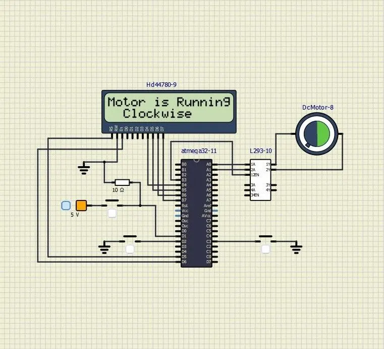
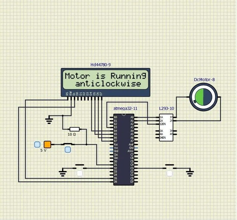
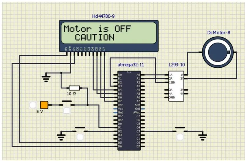
Implement a system on the simulator for controlling a DC motor using L293 motor driver, monitor its status and print the running status of motor on the LCD Display
Goals:
- Implement a system on simulator for Controlling the DC motor using L293 motor driver.
- Displaying the running status of the DC motor on the LCD display.
Hardware to be selected :
- AT Mega 32
- 2*16 LCD(HD44780)
- DC Motor
- 10K Resistor
- L293 Motor driver
- Voltage Source
- Push buttons
Calculation
For 25% of Duty Cycle
Duty cycle = total ON period/( total ON period+ total OFF period)
Duty cycle = 1/4
We have 8 bit PWM ,we will use Timer2 for PWM phase correct mode and i.e. 8 bit timer
Range for 8 bit timer is 0 - 255
value that resister hold = (1/4)*255=63.75=64
We will initially load this value to OCR0 and gradually increase the value using the push button and thereby speed of the motor
so
OCR =64 for 25% of duty cycle
OCR =127 For 50% of duty cycle
OCR =191 For 75% of duty cycle
OCR =255 For 100% of duty cycle
Code
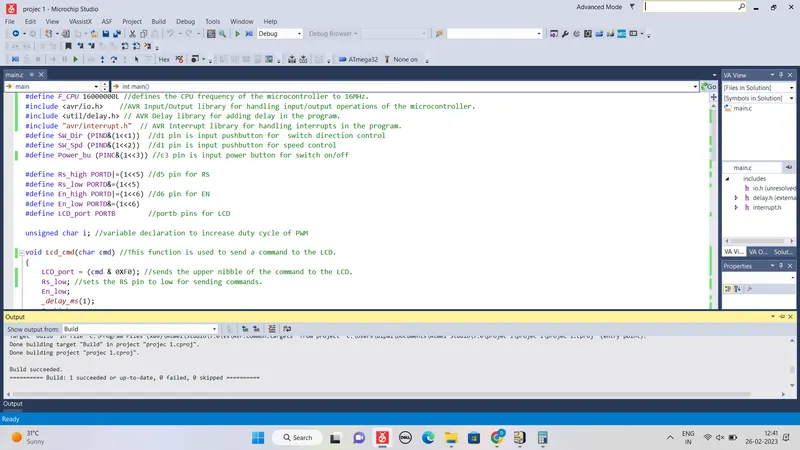
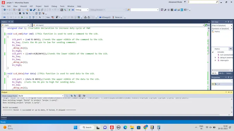
#define F_CPU 16000000L //defines the CPU frequency of the microcontroller to 16MHz.
#include <avr/io.h> //AVR Input/Output library for handling input/output operations of the microcontroller.
#include <util/delay.h> // AVR Delay library for adding delay in the program.
#include "avr/interrupt.h" // AVR Interrupt library for handling interrupts in the program.
#define SW_Dir (PIND&(1<<1)) //d1 pin is input pushbutton for switch direction control
#define SW_Spd (PIND&(1<<2)) //d1 pin is input pushbutton for speed control
#define Power_bu (PINC&(1<<3)) //c3 pin is input power button for switch on/off
#define Rs_high PORTD|=(1<<5) //d5 pin for RS
#define Rs_low PORTD&=(1<<5)
#define En_high PORTD|=(1<<6) //d6 pin for EN
#define En_low PORTD&=(1<<6)
#define LCD_port PORTB //portb pins for LCD
unsigned char i; //variable declaration to increase duty cycle of PWM
void Lcd_cmd(char cmd) //This function is used to send a command to the LCD.
{
LCD_port = (cmd & 0XF0); //sends the upper nibble of the command to the LCD.
Rs_low; //sets the RS pin to low for sending commands.
En_low;
_delay_ms(1);
En_high;
LCD_port = ((cmd<<4)&(0XF0));//sends the lower nibble of the command to the LCD.
Rs_low;
En_low;
_delay_ms(1);
En_high;
}
void Lcd_data(char data) //This function is used to send data to the LCD.
{
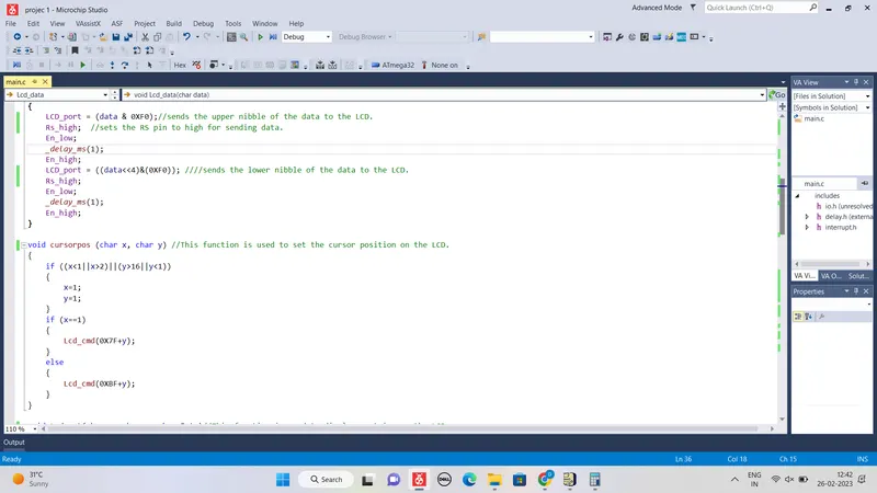
LCD_port = (data & 0XF0);//sends the upper nibble of the data to the LCD.
Rs_high; //sets the RS pin to high for sending data.
En_low;
_delay_ms(1);
En_high;
LCD_port = ((data<<4)&(0XF0)); ////sends the lower nibble of the data to the LCD.
Rs_high;
En_low;
_delay_ms(1);
En_high;
}
void cursorpos (char x, char y) //This function is used to set the cursor position on the LCD.
{
if ((x<1||x>2)||(y>16||y<1))
{
x=1;
y=1;
}
if (x==1)
{
Lcd_cmd(0X7F+y);
}
else
{
Lcd_cmd(0XBF+y);
}
}
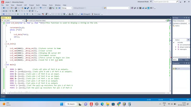
void Lcd_out(char x, char y, char *str)//This function is used to display a string on the LCD.
{
cursorpos(x,y);
while (*str)
{
Lcd_data(*str);
str++;
}
}
Lcd_Init()
{
Lcd_cmd(0X02); _delay_ms(5); //return cursor to home
Lcd_cmd(0X01); _delay_ms(5); //clear screen
Lcd_cmd(0X0C); _delay_ms(5); //display ON cursor OFF
Lcd_cmd(0X06); _delay_ms(5); //increment cursor
Lcd_cmd(0X80); _delay_ms(5); //force cursor to begin 1st line
Lcd_cmd(0X28); _delay_ms(5); //used for 4 bit lcd mode
}
int main()
{
DDRB |= 0XFF; //sets all pins of Port B as outputs.
DDRA |= (1<<0)|(1<<1); //sets pins 0 and 1 of Port A as outputs.
DDRD &= (1<<1); //sets pin 1 of Port D as an input.
DDRD &= (1<<2); //sets pin 2 of Port D as an input.
DDRC &= (1<<3); //sets pin 3 of Port c as an input.
DDRD |= (1<<5); //set pins 5 of Port D as outputs
DDRD |= (1<<6); //set pins 6 of Port D as outputs
PORTD |= (1<<2); //set the pull-up resistors for pin 2 of Port D
PORTC |= (1<<3);//set the pull-up resistors for pin 3 of Port D
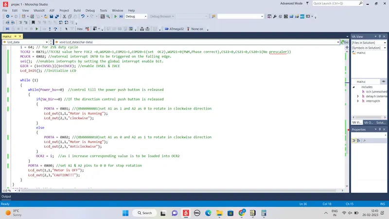
i = 64; // for 25% duty cycle
TCCR2 = 0X71;//TCCR2 values are here FOC2 =0,WGM20=1,COM21=1,COM20=1(set OC2),WGM21=0(PWM,Phase correct),CS22=0,CS21=0,CS20=1(No prescaler))
MCUCR = 0X02; //external interrupt INT0 to be triggered on the falling edge.
sei(); //enables interrupts by setting the global interrupt enable bit.
GICR = (1<<IVSEL)|(1<<IVCE); //enable IVSEL & IVCE
Lcd_Init(); //Initialize LCD
while (1)
{
while(Power_bu==0) //control till the power push button is released
{
if(SW_Dir==0) //If the direction control push button is released
{
PORTA = 0X01; //(0b00000001)set A1 as 1 and A2 as 0 to rotate in clockwise direction
Lcd_out(1,1,"Motor is Running");
Lcd_out(2,3,"clockwise");
}
else
{
PORTA = 0X02; //(0b00000010)set A1 as 0 and A2 as 1 to rotate in clockwise direction
Lcd_out(1,1,"Motor is Running");
Lcd_out(2,3,"Anticlockwise");
}
OCR2 = i; //as i increase corresponding value is to be loaded into OCR2
}
PORTA = 0X00; //set A1 & A2 pins to 0 0 to stop rotation
Lcd_out(1,1,"Motor is OFF");
Lcd_out(2,3,"CAUTION!!!");
}
}
ISR(INT0_vect) //interrupt service routine
{
i = i+64; // i will increase by 64 duty cycle will increase from 25% - 50% - 75% - 100% in each push
}
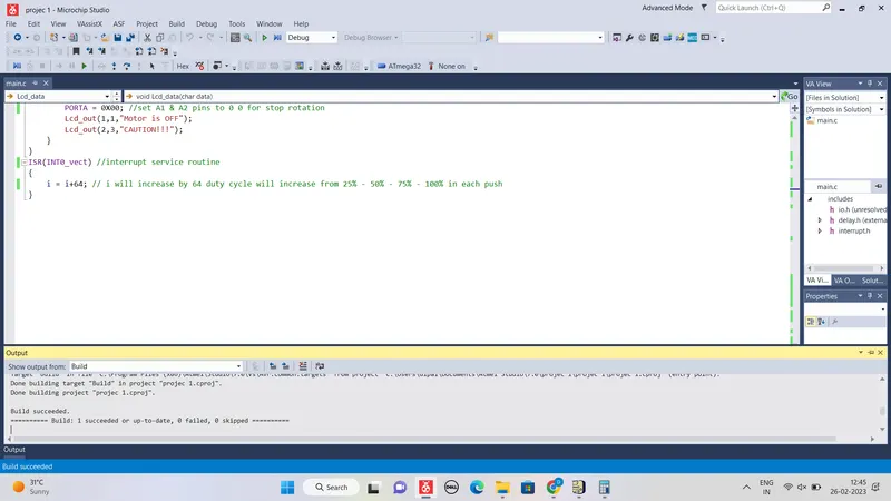
Simulation Circuit