Project 1 - Controlling a DC motor using PWM and monitoring its Running status
Q. Controlling a DC motor using PWM and monitoring its Running status
ANS.
#include
#define F_CPU 16000000L
#include
#define RS_LOW PORTB &= ~(1<<2); //DEFINE BIT FOR RS_LOW
#define RS_HIGH PORTB |=(1<<2); //DEFINE BIT FOR RS_HIGH
#define EN_LOW PORTB &= ~(1<<3);//DEFINE BIT FOR EN_LOW
#define EN_HIGH PORTB |=(1<<3);//DEFINE BIT FOR EN_HIGH
void motor_direction(int status, int delay) //PROGRAM FOR MOTOR DIRECTION
{
OCR0A = delay; //TAKE DELAY
PORTB = 0x40; //ENABLE L293 CHIP
if(status == 0) //for off
{
PORTB &= ~(1<<0);
PORTB &= ~(1<<1);
}
if(status == 1) //for forward direction
{
PORTB |= (1<<0);
PORTB &= ~(1<<1);
}
if(status == -1) //for reverse direction
{
PORTB &= ~(1<<0);
PORTB |= (1<<1);
}
}
void motor_timer0() //MOTOR TIMER
{
DDRB = 0xff; //MAKE PORT D AS OUTPUTP;
TCCR0A = 0b00000011; // select mode fast PWM
TCCR0B = 0b00000001; // set prescaler
OCR0A = 68;
motor_direction(0, 150);
}
void lcd_cmd(unsigned char cmd)
{
PORTD = cmd;
RS_LOW; //FOR SET TO COMMAND MODE
EN_LOW; //CREATE CLOCK SIGNAL
_delay_ms(5);
EN_HIGH;
}
void lcd_data(unsigned char data)
{
PORTD = data;
RS_HIGH; //SET TO DATA
EN_LOW; // CREATE CLOCK SIGNAL
_delay_ms(5);
EN_HIGH;
}
void lcd_init()
{
lcd_cmd(0x38); _delay_ms(5);
lcd_cmd(0x38); _delay_ms(5);
lcd_cmd(0x38); _delay_ms(5);
lcd_cmd(0x38); _delay_ms(5);
lcd_cmd(0x0c); _delay_ms(5);
lcd_cmd(0x01); _delay_ms(5);
lcd_cmd(0x06); _delay_ms(5);
lcd_cmd(0x80); _delay_ms(5);
}
void cursor_position(char x, char y)//SET THE CURSOR POINT
{
if((x < 1 | x > 2)||(y < 1 | y > 16))
{
x=1;
y=1;
}
if(x==1)
{
lcd_cmd(0x7f+y);
}
else
{
lcd_cmd(0xbf+y);
}
}
void lcd_out(char a, char b, char *str)//PRINT IN LCD
{
cursor_position(a,b);
while(*str)
{
lcd_data(*str);
str++;
}
}
int main(void)
{
DDRC = 0x00; //MAKE PORT C PIN 1,0 AS INPUT
PORTC = 0xff ; // ACTIVATE THE PULL UP RESISTOR
lcd_init();
motor_timer0();
char g[20] = "motor stop";
lcd_out(1,1, &g);
_delay_ms(500);
while(1)
{
if((PINC & (0x01)) == 0)
{
motor_direction(1,80); // MOTOR DIRECTION CALL
lcd_cmd(0x01); //CLEAR SCREEN
lcd_cmd(0x01);
char d[20] = "rotate anti_cw"; //SEND TO LCD
lcd_out(1,1, &d);
_delay_ms(500);
}
if((PINC & (0x02)) ==0)
{
motor_direction(-1,80); //MOTOR DIRECTION CALL
lcd_cmd(0x01); //CLEAR SCREEN
lcd_cmd(0x01);
char c[20] ="rotate cw"; //SEND TO LCD
lcd_out(1,1,&c);
_delay_ms(500);
}
}
}
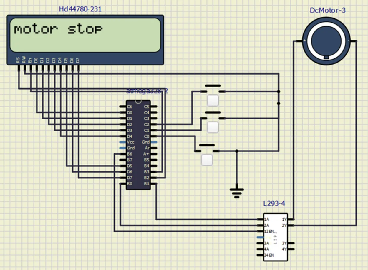
circuit diagram of project.
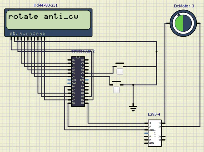
SHOWN ON LED SCREEN THAT MOTOR MOVES in ANTI CLOCKWISE DIRECTIOn WHEN PRESSED THIRD BUTTON:
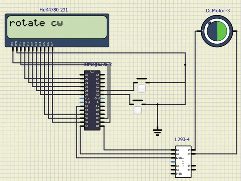
ON LED SCREEN THAT MOTOR MOVES iN CLOCKWISE DIRECTION WHEN PRESSED SECOND BUTTON:
SHOWN ON LED SCREEN THAT MOTOR IS STOP WHEN PRESSED FIRST BUTTON: