Project 1 - Controlling a DC motor using PWM and monitoring its Running status
Aim:
To implement a system on the simulator for controlling a DC motor using L293 motor driver, monitor its status and print the running status of motor on the LCD Display.
Objective:
- Implement a system on simulator for Controlling the DC motor using L293 motor driver.
- Displaying the running status of DC motor on the LCD display.
DC Motor:
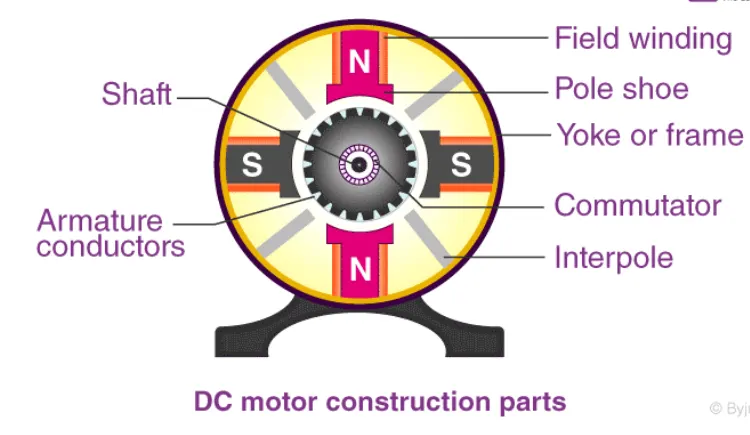
- A DC motor is defined as a class of electrical motors that convert direct current electrical energy into mechanical energy.
- When kept in a magnetic field, a current-carrying conductor gains torque and develops a tendency to move.
- Thus when electric fields and magnetic fields interact, a mechanical force arises.
- This is the principle on which the DC motors work.
L293 Motor Driver:
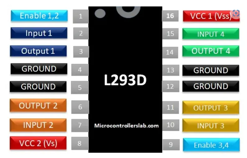
- L293d IC is known as a motor driver.
- It is a low voltage operating device like other ICs.
- The other ICs could have the same functions like L293d but they cannot provide the high voltage to the motor.
- L293d provides the continuous bidirectional Direct Current to the Motor.
- The Polarity of current can change at any time without affecting the whole IC or any other device in the circuit.
- L293d has an internal H-bridge installed for two motors.
Code:
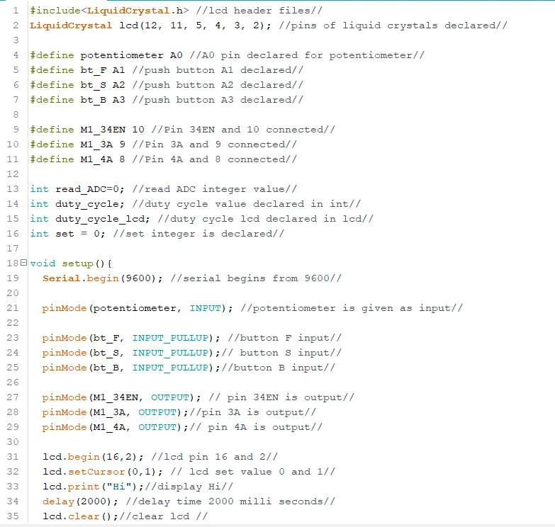
#include
LiquidCrystal lcd(12, 11, 5, 4, 3, 2);

#define potentiometer A0
#define bt_F A1
#define bt_S A2
#define bt_B A3

#define M1_34EN 10
#define M1_3A 9
#define M1_4A 8

int read_ADC=0;
int duty_cycle;
int duty_cycle_lcd;
int set = 0;

void setup(){
  Serial.begin(9600);

  pinMode(potentiometer, INPUT);

  pinMode(bt_F, INPUT_PULLUP);
  pinMode(bt_S, INPUT_PULLUP);
  pinMode(bt_B, INPUT_PULLUP);

  pinMode(M1_34EN, OUTPUT);
  pinMode(M1_3A, OUTPUT);
  pinMode(M1_4A, OUTPUT);

  lcd.begin(16,2);
  lcd.setCursor(0,1);
  lcd.print("Hi");
  delay(2000);
  lcd.clear();
}

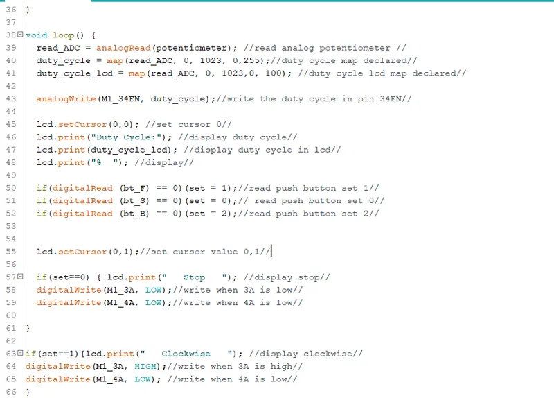
void loop() {
  read_ADC = analogRead(potentiometer);
  duty_cycle = map(read_ADC, 0, 1023, 0,255);
  duty_cycle_lcd = map(read_ADC, 0, 1023,0, 100);

  analogWrite(M1_34EN, duty_cycle);

  lcd.setCursor(0,0);
  lcd.print("Duty Cycle:");
  lcd.print(duty_cycle_lcd);
  lcd.print("%  ");

  if(digitalRead (bt_F) == 0)(set = 1);
  if(digitalRead (bt_S) == 0)(set = 0);
  if(digitalRead (bt_B) == 0)(set = 2);


  lcd.setCursor(0,1);

  if(set==0) { lcd.print("   Stop   ");
  digitalWrite(M1_3A, LOW);
  digitalWrite(M1_4A, LOW);

}

if(set==1){lcd.print("   Clockwise   ");
digitalWrite(M1_3A, HIGH);
digitalWrite(M1_4A, LOW);
}
if(set==2){lcd.print("   Anticlockwise   ");
digitalWrite(M1_3A, LOW);
digitalWrite(M1_4A, HIGH);
}

delay(50);
}
Program:

Circuit:
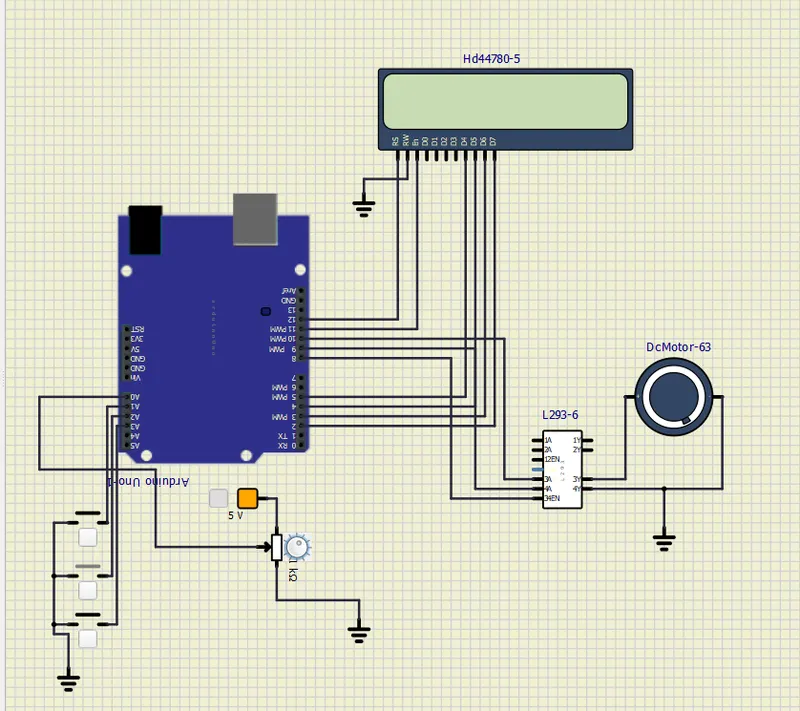
- The push button are connected to A1,A2 and A3 pin of Arduino chip.
- Pin A0 is connected to potentiometer with a 5V supply and ground terminal.
- The motor drive L293 , DC motor and LCD display are connected to Arduino board as shown in the above figure.
Output:
Set ==0
(3A = low, 4A = low)
Set ==1
(3A = high, 4A = low)
Set ==2
(3A = low, 4A = high)
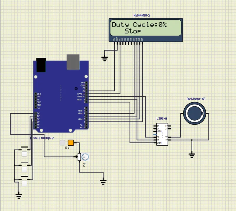
- By varying the potentiometer the duty cycle is varied.
- The rotation of the motor can be changed by pressing the push buttons respectively.
- Stop ,Clockwise and Anticlockwise rotations are the three modes of operation displayed in the LCD.
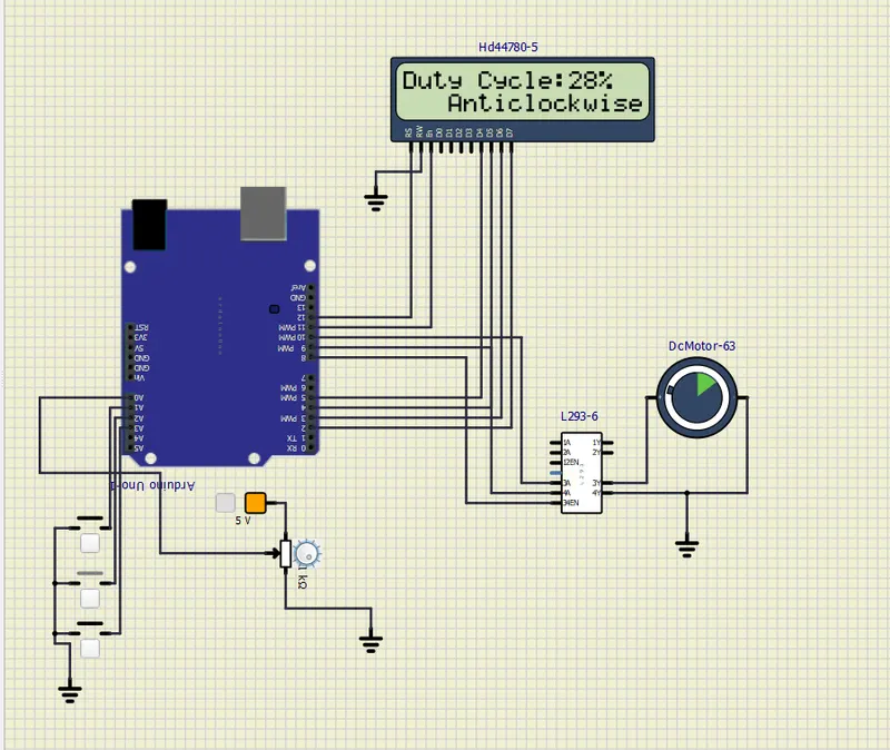
Anticlockwise direction with 28% duty cycle:
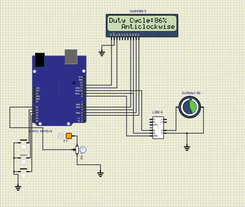
With 86% duty cycle:
Result:
- Thus implemented a system on simulator to control a DC motor using PMW.
- Monitoring the running status of the DC motor using L293 motor driver which allows the DC motor to drive on any direction.
- Running status i.e. on which direction the DC motor is running is to be displayed on the LCD screen.