Controlling a DC motor using PWM and monitoring its Running status
Overview of the Project:
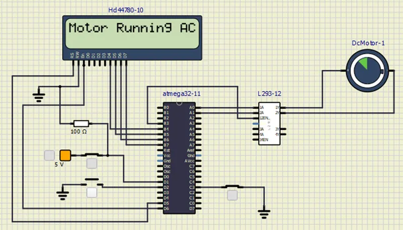
Implement a system on the simulator for controlling a DC motor using L293 motor driver, monitor its status and print the running status of motor on the LCD Display.
LIST OF COMPONENTS:
- Atmega 32
- 2*16 LCD (HD44780)
- DC Motor (12v)
- 10k Resistor
- L293 Motor Driver
- Voltage source
- Push buttons
WORKING :
L293 Motor Driver
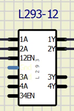
In Simulation, we don’t need to give the motor supply current and the driver needs the driver pin, as we do in hardware implementation.
- 1A and 2B : These terminals decide the direction of rotation of the motor. Writing 1, 0 to these pins respectively drive the motor in clockwise direction. And writing 0,1 responsible for the anti clockwise rotation. Writing 11 or 00 as no turning effect.
- 1y and 2y terminals are to be connected to the terminals of the dc motor.
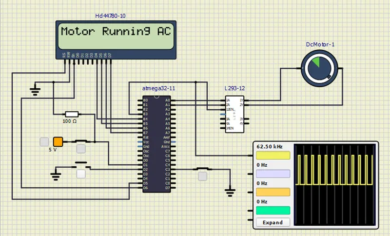
- Enable pins are also used to control the speed of the DC motor. If you apply PWM signal to these enable pins, then the motor driver IC L293D can control the speed of both Motors.
PWM To Drive DC Motor
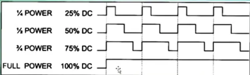
Speed of a motor is directly affected by three factors. Load voltage and current. For a given load, we can maintain a steady speed by using a method called PWM(pulse width modulation).By varying the width of the pulse applied to the DC motor. We can vary the power applied to the DC motor and thereby increase / decrease the motor speed. That means wider the pulse, higher will be the duty cycle.
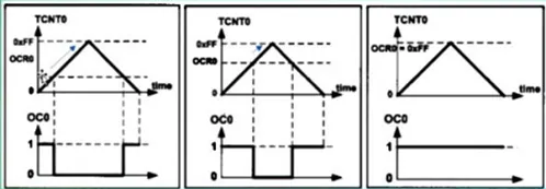
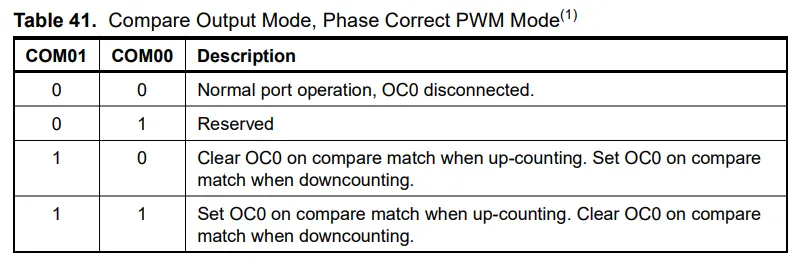
The phase correct PWM mode (WGM [1:0]=1) allow us a high resolution phase correct PWM waveform generation choice. The counter counts again and again from BOTTOM to MAX and then form MAX to BOTTOM. In non inverting compare output mode, OC0 is cleared on the compare match between TCNT0 and OC0 while upcounting and set on the compare match while downcounting. The dual slope operation as lower maximum operation frequency than single slope operation. Thus, Dual slope operation as Lower maximum operation frequency than slope single slope operation. Thus, due to symmetric feature of a dual slope, BWM modes, these modes are preferred for motor control applications.
Datas from the data sheet of Atmega32
Note that, as the values of OCR 0 increases, the on time also increases in non inverting mode of phase correct PWM mode. Phase Correct PWM mode has an 8 bits resolutions. In phase correct PWM mode, the counter is incremented until the counter value matches MAX. When the counter reaches MAX, it changes the count direction. The TCNT0 value will be equal toMAX for one Clock cycle. The TCNT0 value will be histogram for illustrating the dual slope operation. The Diagram includes non inverted and inverted PWM outputs. The small horizontal line marks on the TCNT0 slopes represent compare matches between OCR0 and TCN.
In this project, we are having 8 bit PWM, which means 256 bits, 25% of 256 as 64. We will initially load this value of OCR0 and gradually increase the value using a push button and thereby speed of the motor.
Duty cycle in % = (2 * OCR0 / 510) * 100
we can also use this formula to calculate the value to be loaded into OCR0.
SIMULATION :
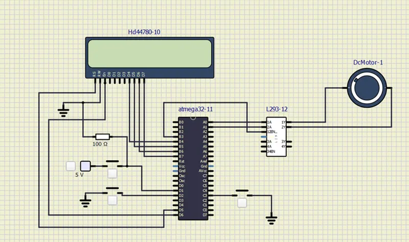
CODE:
#include <avr/io.h> //we are using the I/O registers of AVR
#define F_CPU 16000000L // define the CPU frequency
#include "avr/interrupt.h" // we are using external interrupt pin
#include <util/delay.h> // delay function
#define sw_dir (PIND & (1<<1)) // d1 pin is declared as switch button for direction control.
#define sw_dspd (PIND & (1<<2)) // d2 pin is declared as push button for speed control.
#define pw (PINC & (1<<3)) // c3 is declared as switch button for power ON/OFF
#define lcd_port PORTB //PORTB pins are dedicated for LCD data
#define RS_high PORTD |= (1<<5) // d5 pin is used for RS
#define RS_low PORTD &=~ (1<<5)
#define EN_high PORTD |= (1<<6) // d6 pin is used for EN
#define EN_low PORTD &=~ (1<<6)
unsigned char i; //variable declared to increase the duty cycle in PWM
void lcd_cmd(char cmd) //command for lcd display
{
lcd_port = (cmd & 0xf0); // Masking 4 bits for 4 bit lcd mode
RS_low;
EN_low;
_delay_ms(1); //after 1ms disable lcd
EN_high; //enable the lcd
lcd_port = ((cmd<<4) & (0xf0)); //lcd port
RS_low;
EN_low;
_delay_ms(1); //after 1ms disable lcd
EN_high; //enable the lcd
}
void lcd_data (char data) //send the data to lcd
{
lcd_port = (data & 0xf0); // Masking 4 bits for 4 bit lcd mode
RS_high; //access data register
EN_low;
_delay_ms(1);
EN_high;
lcd_port = ((data<<4) & (0xf0)); //4 bits for 4 bit lcd mode
RS_high; //access data register
EN_low;
_delay_ms(1);
EN_high;
}
void lcd_init()
{
lcd_cmd(0x28);// used for 4 bit lcd mode
_delay_ms(5);
lcd_cmd(0x02); // return home
_delay_ms(5);
lcd_cmd(0x01); // clear screen
_delay_ms(5);
lcd_cmd(0x0C); // display on cursor off
_delay_ms(5);
lcd_cmd(0x06); // increment the display cursor
_delay_ms(5);
lcd_cmd(0x80); // force cursor to begin from 1st line
_delay_ms(5);
}
void cursorpos(char x,char y)
{
if((x<1 || x>2) || (y>16 || y<1 )) //condition will checks the 2 rows and 16 columns
{
x=1; //x= row
y=1; //y= column
}
if(x==1)
{
lcd_cmd(0x7F + y); //{ 80-1 = 7F} for starting the 1st line hex decimal value (80) we are using 7f+y as need to start from that column
}
else //(x==2)
{
lcd_cmd(0xBF + y); //{0C-1 = 0B} for starting the 2nd line, 2nd row
}
}
void lcd_out(char x, char y, char *str) //here we are checking which position we want to print
{
cursorpos(x,y);
while(*str)
{
lcd_data(*str);
str++;
}
}
int main(void)
{
DDRB = 0XFF; //Declaring all 8-pins as output
DDRA |= ((1<<0)| (1<<1)); //Declaring A0 & A1 pins as output
DDRD &=~ (1<<1); //Declaring D1 pin as input
DDRD &=~ (1<<2); //Declaring D2 pin as input
DDRD |= (1<<5); //Declaring D5 pin as output
DDRD |= (1<<6); //Declaring D6 pin as output
DDRC &=~ (1<<3); //Declaring C3 pin as input
PORTD |= (1<<2); //enabling internal pull up resistor for D2
PORTC |= (1<<3); //enabling internal pull up resistor for D3
i=64; //initializing i=64 because we are running the motor with 25% duty cycle
TCCR0=0X61; //Non-Inverting mode, PWM phase correct mode,NO prescalar
GICR=(1<<INT0); //using INT0 for interrupt
MCUCR=0X02; //make interrupt negative edge triggered
sei(); //Enable global interrupt
lcd_init(); //Initialize lcd
while(1)
{
while(pw==0) //continue till the push button is released.
{
if(sw_dir == 0) //if the direction control push button is released.
{
PORTA = 0b00000001; // 1 0 to respective 1A 2A pins to rotate in clockwise direction.
lcd_out(1,1,"Motor Running CL"); //Running clock wise direction
}
else
{
PORTA = 0b00000010; // 1 0 to respective 1A 2A pins to rotate in Anti-Clockwise direction.
lcd_out(1,1,"Motor Running ACL"); //Running Anticlock wise direction
}
OCR0 = i; //i increases in ISR, the corresponding value is to be loaded into OCR0.
}
PORTA = 0x00; // 0 0 to respective 1A 2A pins to Stop rotation.
lcd_out(1,1,"Motor is TURNOFF"); //motor is turnoff
}
}
ISR(INT0_vect) //interrupt service routine
{
i=i+20; /* as i increases the duty cycle also increases. i increases by 20 in each push
and the corresponding value is to be loaded into OCR0 in while loop*/
}
OUTPUT :
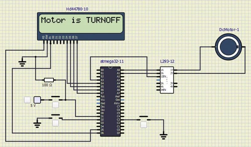
When Power Switch-Off, Direction Switch-Off,Speed Switch-Off: Motor is Turn Off Condition
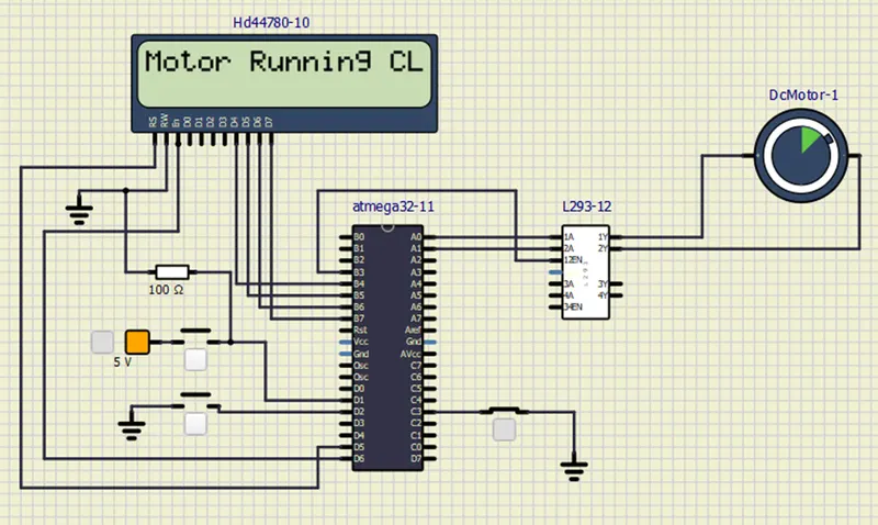
When Power Switch-On, Direction Switch-Off,Speed Switch-Off: Motor is Turn On Condition and Motor is running clockwise direction
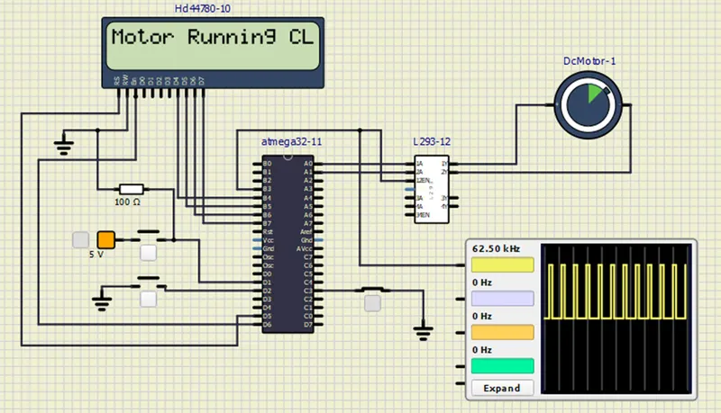 When Power Switch-On, Direction Switch-On,Speed Switch-Off: Motor is Turn Off Condition and Motor is runnig Anticlockwise direction
RESULT:
- Thus implemented a system on simulator to control a DC motor using PMW.
- Monitoring the running status of the DC motor using L293 motor driver which allows the DC motor to drive on any direction.
- Running status i.e. on which direction the DC motor is running is to be displayed on the LCD screen.