Project 1 - Controlling a DC motor using PWM and monitoring its Running status
Aim:
To control a DC motor using PWM and to monitor its running status on LCD.
Tools Used :
1.Atmega 32
2. L293 Motor driver
3. Push buttons 3 one for controlling the direction, one for speed and the other for turning on and off.
4. Lcd display
5. Dc Motor
About L293:
L293D is a 16 Pin Motor Driver IC. This is designed to provide bidirectional drive currents at voltages from 5 V to 36 V.
Pin 1: When Enable1/2 is HIGH, Left part of IC will work, i.e motor connected with pin 3 and pin 6 will rotate.
Pin 2: Input 1, when this pin is HIGH the current will flow though output 1.
Pin 3: Output 1, this pin is connected with one terminal of motor.
Pin 4/5: GND pins
Pin 6: Output 2, this pin is connected with one terminal of motor.
Pin 7: Input 2, when this pin is HIGH the current will flow though output 2.
Pin 8: VSS, this pin is used to give power supply to connected motors from 5V to 36V maximum depends on Motor connected.
Pin 9: When Enable 3/4 is HIGH, Right part of IC will work, i.e motor connected with pin 11 and pin 14 will rotate.
Pin 10: Input 4, when this pin is HIGH the current will flow though output 4.
Pin 11: Output 4, this pin is connected with one terminal of motor.
Pin 12/13: GND pins
Pin 14: Output 3, this pin is connected with one terminal of motor.
Pin 15: Input 3, when this pin is HIGH the current will flow though output 3.
Pin 16: VCC, for supply power to IC i.e 5V.
PWM SIGNAL :
The DC motor speed in general is directly proportional to the supply voltage, so if reduce the voltage from 9 volts to 4.5 volts then our speed become half of what it originally had. But in practice, for changing the speed of a dc motor we cannot go on changing the supply voltage all the time. The speed controller PWM for a DC motor works by varying the average voltage supplied to the motor
LCD display :
The HD44780U dot-matrix liquid crystal display controller and driver LSI displays alphanumerics
and symbols. It can be configured to drive a dot-matrix liquid crystal display
under the control of a 4- or 8-bit microprocessor. Since all the functions such as display RAM, character
generator, and liquid crystal driver, required for driving a dot-matrix liquid crystal display are internally
provided on one chip, a minimal system can be interfaced with this controller/driver.
A single HD44780U can display up to one 8-character line or two 8-character lines.
About the Project:
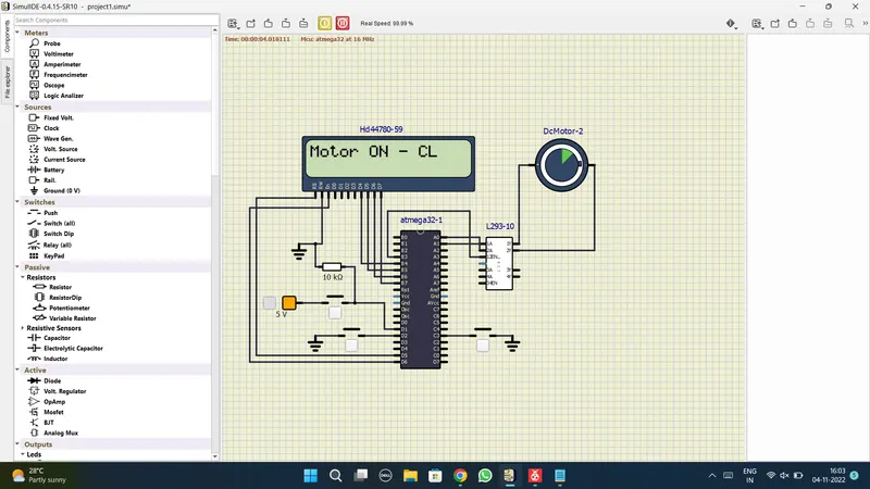
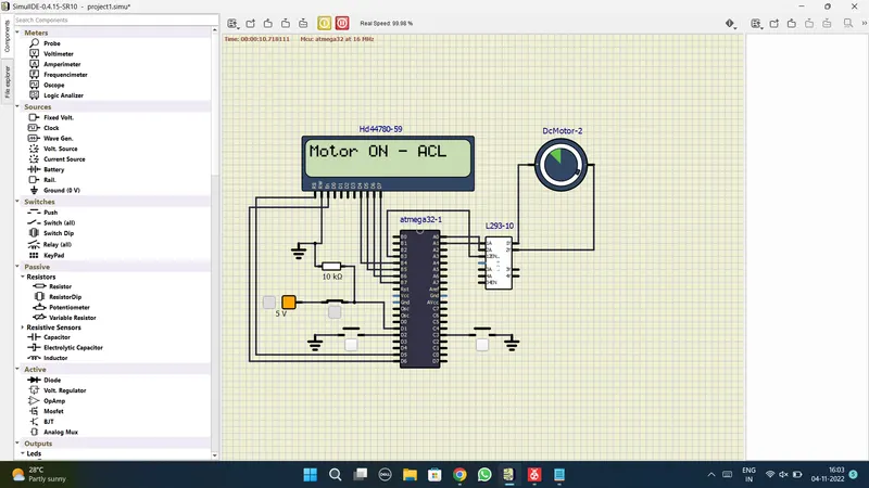
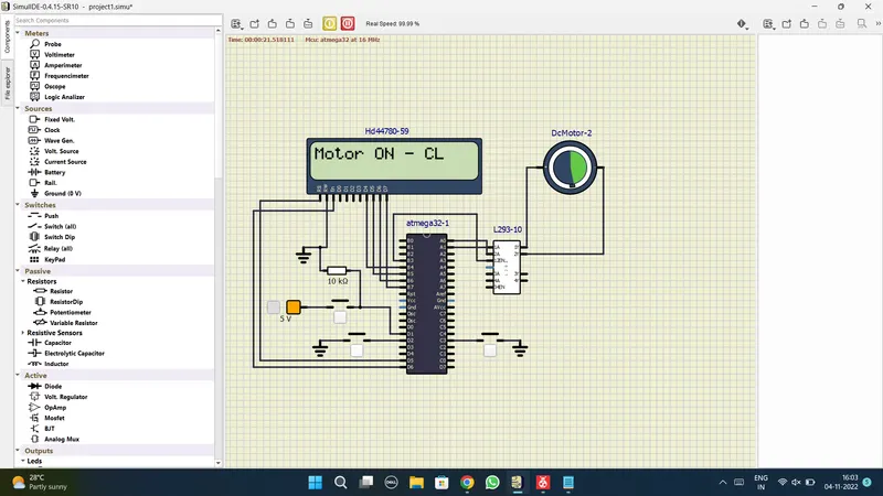
In this project, we are interfacing atmega 32 with an LCD display, which displays the running status of a motor we have connected a motor with the microcontroller with the help of L29 3D motor, which rotates the motor in clockwise and anti clockwise direction. And the direction is displayed on the LCD displays if it is rotating in clockwise direction and anticlockwise direction, we have used a push button, which acts like an interrupt and with the help of which we can increase the duty cycle, which means we can increase the speed of the motor.
Program Used:
/*
* projectmotor.c
*
* Created: 04-11-2022 15:53:52
* Author : maaza
*/
#include <avr/io.h> //I/O registers of AVR
#define F_CPU 16000000L // crystal frequency
#include <avr/interrupt.h> // for external interrupt pin
#include <util/delay.h> // adding delay
#define sw_dir (PIND & (1<<1)) // d1 pin as push button for direction control.
#define sw_dspd (PIND & (1<<2)) // d2 pin as push button for speed control.
#define pw (PINC & (1<<3)) // c3 is declared as push button for power on and off
#define lcd_port PORTB //PORTB pins are for LCD
#define RS_high PORTD |= (1<<5) // d5 pin is used for register select
#define RS_low PORTD &=~ (1<<5)
#define EN_high PORTD |= (1<<6) // d6 pin is used for Enable
#define EN_low PORTD &=~ (1<<6)
unsigned char i;
void lcd_cmd(char cmd) //for lcd display
{
lcd_port = (cmd & 0xf0); //configuring 4 bits for 4 bit lcd mode
RS_low;
EN_low;
_delay_ms(1);
EN_high;
lcd_port = ((cmd<<4) & (0xf0)); //lcd port
RS_low;
EN_low;
_delay_ms(1);
EN_high;
}
void lcd_data (char data) //sending data to lcd
{
lcd_port = (data & 0xf0);
RS_high; //access data register
EN_low;
_delay_ms(1);
EN_high;
lcd_port = ((data<<4) & (0xf0));
RS_high;
EN_low;
_delay_ms(1);
EN_high;
}
void lcd_init()
{
lcd_cmd(0x28);// used for 4 bit lcd mode
_delay_ms(5);
lcd_cmd(0x02); // return home
_delay_ms(5);
lcd_cmd(0x01); // clear screen
_delay_ms(5);
lcd_cmd(0x0C); // display on cursor off
_delay_ms(5);
lcd_cmd(0x06); // increment the display cursor
_delay_ms(5);
lcd_cmd(0x80); // force cursor to begin from 1st line
_delay_ms(5);
}
void cursorpos(char x,char y)
{
if((x<1 || x>2) || (y>16 || y<1 )) //condition will check the 2 rows and 16 columns
{
x=1; //x= row
y=1; //y= column
}
if(x==1)
{
lcd_cmd(0x7F + y); //{ 80-1 = 7F} for starting the 1st line
}
else //(x==2)
{
lcd_cmd(0xBF + y); //{0C-1 = 0B} for starting the 2nd line
}
}
void lcd_out(char x, char y, char *str) //checking position we want to print
{
cursorpos(x,y);
while(*str)
{
lcd_data(*str);
str++;
}
}
int adc_read(char channel) // configuring adc value
{
unsigned int a, result;
ADMUX = channel; // selecting 2 bit in mux
ADCSRA = 0X80; //for enable interrupt flag
ADCH = 0X00; // clear register
ADCL = 0x00;
ADCSRA |= (1<<6); // to start the conversion 6 bit ADSC high
while((ADCSRA & 0x40) != 0);
a= ADCL; //dummy data type a
result = ADCH; // Store the high value
result = result<<8; //left shift for proper result
result = result | a ; //adding to get 16bit
return result;
}
int main(void)
{
DDRB = 0XFF; //Declaring whole port as output
DDRA |= ((1<<0)| (1<<1)); //Declaring A0 & A1 pins as output.
DDRD &=~ (1<<1); //Declaring D1 pin as input.
DDRD &=~ (1<<2); //Declaring D2 pin as input.
DDRD |= (1<<5); //Declaring D5 pin as output.
DDRD |= (1<<6); //Declaring D6 pin as output.
DDRC &=~ (1<<3); //Declaring C3 pin as input.
PORTD |= (1<<2); //enabling internal pull up resistor for D2.
PORTC |= (1<<3); //enabling internal pull up resistor for D3.
i=64; //initializing i=64 because we are running the motor with 25% duty cycle.
TCCR0=0X61; //selecting PWM phase correct mode
GICR=(1<<INT0); //using INT0 for interrupt
MCUCR=0X02; //make interrupt negative edge triggered
sei(); //Enable global interrupt
lcd_init(); //Initialize lcd
while (1)
{
while(pw==0) //continue till the push button is released.
{
if(sw_dir == 0) //if the direction control push button is released.
{
PORTA = 0b00000001; // setting 1 0 to respective 1A 2A pins to rotate in clockwise direction.
lcd_out(1,1,"Motor ON - CL ");
}
else
{
PORTA = 0b00000010; // setting 1 0 to respective 1A 2A pins to rotate in Anti-Clockwise direction.
lcd_out(1,1,"Motor ON - ACL");
}
OCR0 = i; //i increases in ISR, the corresponding value is to be loaded into OCR0.
}
PORTA = 0x00; //setting 0 0 to respective 1A 2A pins to Stop rotation.
lcd_out(1,1,"Motor is OFF");
}
}
ISR(INT0_vect) //interrupt service routine
{
i=i+25; // as i increases the duty cycle also increases. i increases by 20 in each push//
// and the corresponding value is to be loaded into OCR0 in while loop//
}
Output Simulation:
EXECUTED PROGRAM IN MICROCHIP
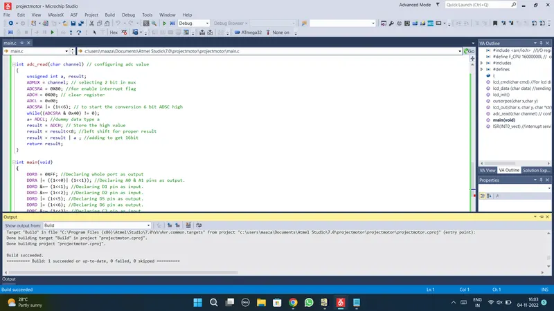
MOTOR IS ON RUNNING IN CLOCKWISE DIRECTION
MOTOR IS ON RUNNING IN ANTICLOCKWISE DIRECTION
MOTOR IS ON RUNNING WITH HIGH SPEED.
MOTOR IS TURNED OFF.
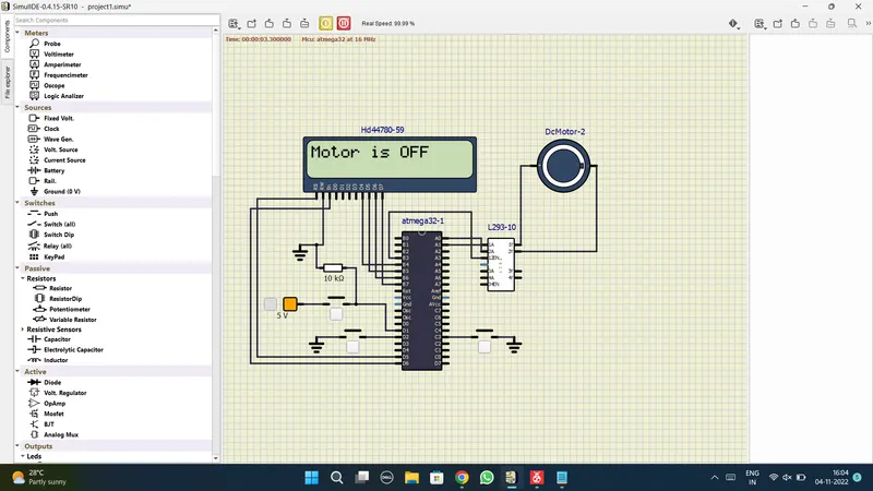
RESULT:
Hence we have successfully configured to control a motor using pwm and also displayed the running status of motor on the LCD display.