Project 1 - Controlling a DC motor using PWM and monitoring its Running status
Aim - Implement a system on the simulator for controlling a DC motor using L293 motor driver, monitor its status and print the running status of motor on the LCD Display.
Software Required - Microchip Studio and simulide.
Components Required - 16*2 LCD Module , Atmega328 uc, l293 motor drover ic, DC Motor,3 push buttons.
Theory -
1)PWM - In power electronics, pulse width modulation is a proven effective technique that is used to control semiconductor devices. Pulse width modulation or PWM is a commonly used control technique that generates analog signals from digital devices such as microcontrollers. The signal thus produced will have a train of pulses, and these pulses will be in the form of square waves. Thus, at any given time, the wave will either be high or low.
Setting Duty cycle: we have to load value in the OCR0 register to set the duty cycle.255 value for 100% duty cycle and 0 for 0% duty cycle. Accordingly, if we load value 127 in OCR0, the Duty cycle will be 50%.
1) TCCR0A - Set as fast PWM Mode 00000011
ATmega328p micrcontroller Timer/Counter can be used to generate PWM signal. There are two types of PWM signal that can be generated which are Fast PWM and Phase Correct PWM. The Fast PWM mode is used for power regulation, rectification, and DAC applications.

Fast PWM mode
The Fast PWM mode is used to generate PWM signal at the output compare pins(either OC0A or OC0B depending upon which output compare unit A or B is used). It is called Fast because the generated PWM signal can have high frequency due to its single-slope operation.
Modes of Fast PWM mode
There are two Fast PWM modes for Timer/Counter 0 unit. They are mode 3 and mode 7 which are selected using the waveform generation mode bits(WGM02, WGM01, WGM00).
2) TCCR0B - Configure no prescaling mode - 00000001 - CS00=1

TCCR0B registor use in no prescaling mode- CS02 - 0,CS01-0, CS00 - 1.
L293 IC -
A motor driver is an integrated circuit chip which is usually used to control motors in autonomous robots. Motor driver act as an interface between Arduino and the motors . The most commonly used motor driver IC’s are from the L293 series such as L293D, L293NE, etc. These ICs are designed to control 2 DC motors simultaneously. L293D consist of two H-bridge. H-bridge is the simplest circuit for controlling a low current rated motor. We will be referring the motor driver IC as L293D only. L293D has 16 pins.
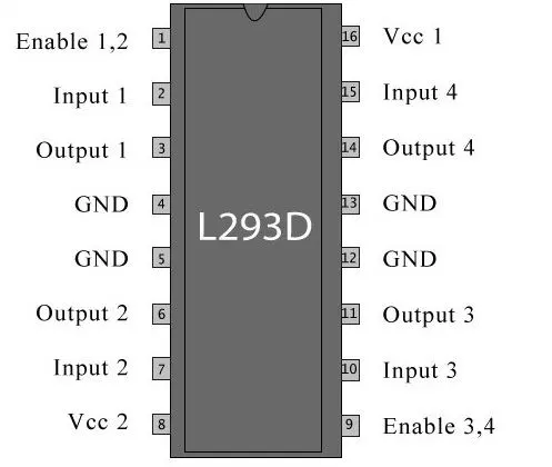
1) The output of atmega328 uc is connected to input pins of L293D Motor driver ic and B0 and B1 pin.
2) B6 Pin is connected for enable the L2N3D IC. This IC used to provide the reqiured Voltage and current to drive the DC Motor because the output of uc is very low. It is not sufficient for drive the motor.
3) The output of L293D is conectecd to DC Motor.
4) The switches is connected to Pin no 0,1 and 2 of PORT C. FOR control the direction of DC Motor according to the logic configure in Software.
5) 16*2 LCD Display is connected to PORTD from D0 -to D7. RS pin is conncted to PB2 and EN is connetced to PB3. and RW pin is conneted to Ground.
6) Display is Display the status of motor. rotating clockwise , anticlockwise or stop mode. given by user and check the logic of switch.